The Role of TLY-5 in High-Frequency PCBs
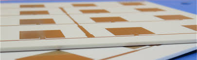
Taconic TLY-5 PCB material is a PTFE-based high-frequency laminate designed to meet the demanding requirements of RF, microwave, and high-speed PCB applications. Its low dielectric loss, stable dielectric constant, and excellent thermal and mechanical properties make it a top choice for wireless communication systems, industrial wireless sensor networks (IWSNs), and aerospace electronics.
By understanding TLY-5’s material properties, design considerations, and fabrication guidelines, engineers can achieve maximum signal integrity, reliable RF performance, and long-term operational stability.
Material Properties of Taconic TLY-5
1. Dielectric Characteristics
- Dielectric constant (Dk): Low and stable across wide frequencies for predictable impedance control.
- Dissipation factor (Df): Ultra-low to minimize insertion loss in RF and microwave circuits.
- Ensures high signal fidelity in critical high-frequency designs.
2. Thermal Performance
- High thermal stability enables reliable operation in elevated temperatures.
- Supports continuous RF operation without warping or degradation.
- Compatible with common PCB assembly and soldering processes.
3. Mechanical Reliability
- Excellent dimensional stability under thermal cycling.
- Resistance to delamination and material creep.
- Supports high-density multilayer PCB designs.
Design Considerations for TLY-5 Laminates
1. Controlled Impedance and Stack-Up
- Maintain precise trace width and spacing to ensure signal integrity.
- Use balanced signal and ground plane stack-ups to reduce crosstalk and EMI.
- Minimize parasitic inductance in high-frequency traces.
2. Multilayer PCB Layout
- Place signal layers close to reference planes for optimal RF performance.
- Carefully plan power and ground planes to reduce insertion loss and maintain low Dk variation.
- Optimize layer count to balance manufacturability and electrical performance.
3. Thermal and Mechanical Management
- Incorporate thermal vias for heat dissipation in high-power RF circuits.
- Consider material expansion coefficients when designing multi-material stack-ups.
- Avoid placing sensitive RF components near heat-generating elements.
Fabrication Guidelines
1. Drilling and Plating
- Use sharp, high-quality drill bits to prevent delamination.
- Maintain tight tolerance on via diameters for controlled impedance.
- Ensure proper plating thickness for signal and power vias.
2. Lamination and Curing
- Follow controlled temperature and pressure profiles to maintain flatness.
- Use compatible prepregs for multilayer boards.
- Avoid excessive heat to prevent warping or resin bleeding.
3. Solder Mask and Surface Finish
- Choose high-temperature solder masks for RF applications.
- ENIG (Electroless Nickel Immersion Gold) finish is preferred for wirebonding and SMD reliability.
- Avoid aggressive chemicals that can degrade PTFE laminates.
4. Component Assembly
- Use low-loss solder paste and controlled reflow profiles.
- Optimize placement of high-frequency components to maintain signal integrity.
- Consider hybrid attachment methods (solder + adhesive) for sensitive modules.
Wirebonding and Device Attachment Notes
- Use gold wirebonding for minimal signal loss.
- Maintain clean, oxide-free bond pads for high reliability.
- Optimize ultrasonic and thermosonic bonding parameters to prevent substrate damage.
- Ensure pad and trace design minimizes parasitic capacitance and inductance.
Applications of Taconic TLY-5 Laminates
- Industrial wireless sensor networks (IWSNs) for factory automation.
- RF modules for 5G and wireless communication infrastructure.
- Aerospace and defense electronics, including radar and satellite systems.
- High-frequency microwave circuits requiring low loss and high signal integrity.
Best Practices for High-Frequency PCB Design
- Select TLY-5 grade suitable for the operating frequency and thermal requirements.
- Maintain controlled impedance across all high-speed traces.
- Optimize stack-up, trace width, and spacing for multilayer designs.
- Implement thermal management techniques, including vias and copper planes.
- Verify post-fabrication performance through electrical and mechanical testing.
Conclusion
Taconic TLY-5 PCB material provides unmatched performance in high-frequency, RF, and microwave applications. By following proper design guidelines, fabrication processes, and assembly techniques, engineers can achieve reliable, low-loss, and high-performance PCB systems suitable for wireless communication, industrial IoT, and aerospace applications.
