Understanding Dielectric Constant: A Beginner’s Guide to Rogers PCB Materials
If you’re stepping into the world of PCB design—especially RF, microwave, or high-frequency systems—you’ll quickly encounter two key concepts: dielectric constant (Dk) and Rogers PCB materials. These are foundational to signal behavior and overall circuit performance.
The dielectric constant describes how a PCB substrate interacts with an electric field, directly influencing signal speed, impedance, and signal integrity. Rogers laminates, known for their low Dk and low loss characteristics, are engineered for applications where standard FR-4 falls short.
This guide breaks down the dielectric constant in practical terms, explores why Rogers materials stand out, and explains how these factors influence RF design. Whether you’re new to PCB engineering or looking to sharpen your understanding, this guide gives you clear and actionable insights.
1. What Is Dielectric Constant and Why Does It Matter?
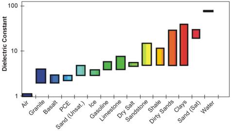
The dielectric constant (Dk) measures how much electrical energy a material can store compared to vacuum. In PCB design, it determines how signals propagate through the substrate.
Why Dk matters:
-
Signal Speed
Lower Dk → faster signal propagation → better performance for high-speed digital & RF. -
Impedance Control
Dk determines the trace width/height required to achieve 50Ω or 75Ω impedance. -
Signal Integrity
A stable Dk across frequency and temperature ensures consistent timing and reduced distortion.
Even small variations in Dk can shift impedance and degrade performance in GHz-level designs.
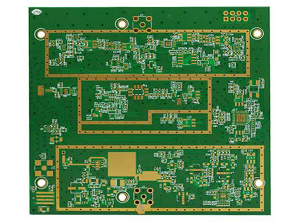
2. Introduction to Rogers PCB Materials
Rogers laminates are high-performance PCB substrates engineered for:
-
low dielectric constant (2.5 – 3.7)
-
ultra-low dissipation factor (Df < 0.002)
-
stable performance over wide temperature & frequency ranges
Compared with conventional FR-4, Rogers provides:
-
lower signal loss
-
reduced phase distortion
-
superior thermal stability
-
predictable material behavior at microwave & mmWave frequencies (e.g., 24GHz, 28GHz, 60GHz)
This makes Rogers materials the standard choice for:
-
5G antennas
-
millimeter-wave radar
-
satellite systems
-
high-frequency amplifiers
-
precision RF sensors
3. Key Electrical Properties That Make Rogers Stand Out
Low Dielectric Constant (Dk)
Enables faster signal propagation and minimizes delay—a must for RF circuits above 1GHz.
Low Dissipation Factor (Df)
Lower Df means less conversion of signal energy into heat. This is critical when transmitting over long traces or high GHz frequencies.
Stable Dk Across Frequency
Some substrates suffer from Dk “drift” at higher GHz ranges—leading to degradation. Rogers maintains predictable performance.
Excellent Thermal & Mechanical Stability
Ensures consistent electrical behavior under harsh conditions and rapid temperature swings.
4. How Dielectric Constant Affects RF Design
Dk plays a central role in RF design:
1. Impedance Matching
Accurate impedance depends heavily on substrate Dk. Lower Dk requires wider traces, affecting layout decisions.
2. Propagation Delay
Signal velocity ≈ c / √Dk
Lower Dk → faster signals → more accurate timing.
3. High-Frequency Losses
Rogers materials significantly reduce dielectric loss and maintain signal strength over long paths.
5. Choosing the Right Rogers Material
Consider the following:
-
Frequency band
Higher frequencies require lower Dk/Df materials (e.g., RO4350B, RO3003). -
Thermal environment
Satellite, automotive radar, and outdoor IoT require materials with minimal thermal drift. -
Cost
Hybrid stackups can balance performance and budget. -
Board thickness
Lower Dk allows thinner substrates while keeping impedance in control.
6. Practical Tips for Beginners
-
Use simulation first (HFSS, ADS, Altium field solver).
-
Design stackup jointly with the PCB fabricator.
-
Account for manufacturing tolerances in Dk.
-
Validate through high-frequency testing.
7. Common Challenges & Solutions
Challenge |
Solution |
|---|---|
| High cost | Use hybrid stackups |
| Complex design rules | Follow Rogers official design notes |
| Material availability | Pre-order materials early |
| Impedance variation | Maintain tight dielectric thickness control |
Conclusion
Mastering dielectric constant is a foundational skill for RF and high-frequency PCB design. Rogers PCB materials provide unmatched stability, low loss, and predictable performance, making them essential for modern high-frequency systems.
With the right knowledge and material selection, your PCB design can achieve exceptional speed, precision, and reliability.
