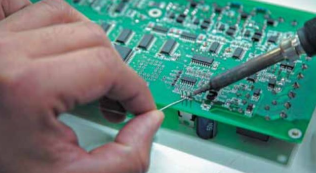
Perfect soldering of a printed circuit board is a very simple, yet very rare, phenomenon. How can this contradiction be explained? If perfect soldering is easy, then why so much rework and rework? The answer, of course, is that it is simple, but only if you know how, and also keep in mind that most of the advice from “soldering experts” is flawed. Following assembly rules that comply with “industry standards” guarantees failures and high costs.
Surprisingly, few people know how to perform reliable soldering, although it is a fundamental process in PCB assembly .
Instead of soldering skills, the excellent skill of concealing defects is often acquired, but this is an entirely different and less useful skill. Visually acceptable connections are not always reliable. The enormous amount of time and money that the electronics assembly industry devotes to training and certifying specialists is largely a waste of resources. No one ever learned perfect soldering by attending “industry standards” training. In this article, I will explain why the reliability of printed circuit board soldering is so dismal and what steps need to be taken to improve the situation.
Why is PCB soldering often not perfect?
The problem is this: training typically focuses on achieving the desired appearance of the solder joint, rather than on producing a high-quality connection. However, an “acceptable” appearance does not guarantee good quality or the absence of errors. The way the connection is made determines whether it is secure and whether irreparable damage has been caused to the soldered electronic component. If the soldering iron is heated excessively and for a long time, the solder will adhere to both oxides and contaminants. Visually, the result of such soldering appears perfectly normal, although in reality, the joint most likely lacks intermetallic bonding, and overheating has destroyed or altered the bonds within the component. This leads to poor electrical performance and a shortened component lifespan. Just a few seconds of improper soldering can reduce the component’s lifespan by years! While the connection may appear to meet specifications, the internal damage to the component is undetectable, meaning the soldering improperly performed process is not detected, and the resulting unfortunate situation continues to recur.
A brief historical overview
Electronics haven’t always been made up of semiconductor components . Decades ago, long before transistors and microprocessors, the cutting-edge technology was vacuum tubes. Electrical connections were made by soldering wires to terminals in sockets into which the tubes were inserted. Some connectors and wires were quite heavy and could absorb significant amounts of heat. Inefficient soldering irons converted the electricity into heat only haphazardly. Therefore, the main challenge during soldering was preventing the solder from solidifying before it could flow where it was needed. Methods developed specifically for this task maximized the amount of heat applied. Heat shielding was not required for the tubes; they were inserted into the sockets only after soldering was complete and were never exposed to the heat of the soldering iron.
The advent of semiconductor components changed this approach. Solder was now applied directly to the component, rather than to a wire or connector terminal. Components became subject to heat during soldering, and this had a significant impact on their reliability: overheating degraded electrical performance. To prevent damage from heat during soldering, metal clips could be attached to the terminals near the component body. The heat from the soldering iron was absorbed and dissipated by the clips before reaching the component body. The clips, called heat sinks, provided reliable protection against overheating. Since the advent of solid-state electronics, every work instruction has included a requirement to use heat sinks (e.g., “IPC J-STD-001G Soldering Requirements for Electronic Assemblies,” Section 4.6). But no one uses heat sinks anymore! How can this be implemented in practice? The terminals, if they exist at all, are too small. There is no room for a heat sink. But all the curricula continue to teach students to clip in like it was 1960.
Reflow is not soldering
And it gets worse. In the years when soldering procedures were being developed, almost all component leads were tin or tin-lead plated. These surfaces melted during soldering, and the molten solder simply flowed down and mixed with the molten metal on the surface being soldered. The oxides, being lighter than the pure metal, floated to the surface of the liquid metals, where they came into contact with flux (which is also lighter than the metal) and were removed. Creating joints by mixing molten metals is a fairly simple process, but it is not soldering. The term “reflowing” was often used more correctly. Soldering (or brazing) is the process of creating an intermetallic bond with metal surfaces that do not melt. They do not “melt” or change their state of aggregation. This requires additional processing steps unnecessary when mixing molten metals. Unfortunately, the term “reflowing” continues to be widely used, although it no longer describes the process.
The difference between soldering and reflow (the mixing of molten metals) became even more pressing when Europe banned lead in electronics. The transition to a lead-free world led to the development of new solder alloys that introduced no significant problems to the process, save for a few quirks. When properly controlled, lead-free solder performs quite well, but it is significantly less tolerant of defects than traditional tin-lead alloys. Since most companies’ PCB soldering processes were already flawed, the transition to new alloys was fraught with difficulties that were mistakenly attributed to the solder rather than the process.
A more serious problem affected metallization. Lead-tin plating was no longer used. But the remaining available tin plating proved to be a poor option due to the high risk of tin whisker defects. As a result, the leads of an increasing number of components (especially multi-pin surface-mount components ) did not reflow at soldering temperatures. This meant they needed to be soldered, not reflowed. However, accepted industry practices often include procedures that only work with reflow. As a result, the most common training programs and certifications simply guarantee defects and failures.
Soldering is a simple science. If you practice it, of course
In practice, soldering is a science, primarily chemistry and metallurgy. The people who created standards and recommendations for soldering methods didn’t view it that way. They acted empirically, failing to understand the obvious: rules must be based on scientific knowledge. They obtained results that seemed correct and codified anecdotal observations into mandatory rules. But if we want the product to work and production to be profitable, the current situation must change. Interestingly, the reliability of an electronic product is inversely proportional to the complexity of the manufacturing process (the amount of processing). The most reliable products are manufactured with the most technologically advanced technology (with the fewest required operations and, consequently, costs). The worst thing in our industry is excessive costs and too many component failures.
Using flux
I mentioned above that perfect soldering is simple. But simplicity doesn’t mean simply slapping molten metal on components and expecting everything to turn out perfectly. Successful soldering requires knowledge and discipline. And the starting point is solderability. As mentioned earlier, until recently, most component leads were plated with tin or tin/lead. Soldering is the process of creating intermetallic bonds with metal surfaces that don’t melt during the application of the connecting material (solder). However, tin and tin/lead melt at PCB soldering temperatures, and the solder simply mixes with the molten coating. This isn’t “soldering,” but “reflow,” a simpler process than true soldering.
Why Reflow is Easy
During reflow, there is no need to remove oxides before applying solder: the oxides, being lighter than the pure metal, float on the mixture of the liquid coating metal and the liquid solder. Flux is also lighter than the liquid metal. It floats on the molten metal and can easily come into contact with and destroy the oxides. During reflow, soldering flux simply makes the final joint shiny and aesthetically pleasing. Most of the prevailing notions about soldering originated during the reflow era. One such belief, with disastrous consequences today, is that liquid flux is unnecessary when hand soldering . It is believed that the flux contained in the solder wire is sufficient to get the job done. While this may be true for reflow, relying solely on the flux in the solder leads to incomplete wetting during soldering.
What are the main defects in printed circuit board soldering?
The ban on lead in electronics has fundamentally changed our industry. Tin-lead mixtures are no longer used, and pure tin is becoming increasingly rare due to the risk of tin whisker defects, which is common in multi-pin surface-mount components such as ICs. The lead surfaces of new components are not tin or tin-lead. These are metals with higher melting points that do not melt when solder is applied. In other words, these are metals that are soldered, not reflowed. Therefore, the surfaces must be thoroughly cleaned before soldering. This will not happen if the flux is contained in the solder wire, as the flux in the solder cannot be released until the solder melts. The molten solder forms a barrier between the flux and the metal surface, preventing complete removal of oxides and causing incomplete wetting.
Solution: Liquid flux
The only way to guarantee that flux reaches the surface oxides before the solder melts is to apply liquid flux first. And more than just a trace amount of flux is required. Flux acid (the part that removes oxides) is neutralized during a chemical deoxidation reaction. Trace amounts of flux will be neutralized before the surface is completely deoxidized. In soldering, flux is more than just a helper—it’s absolutely essential. Yet, industry “experts” often recommend against using liquid flux.
Heating control
The basic principles of soldering—the methods still used today—emerged about 70 years ago. As noted, at the time, the most advanced electronic components were built with vacuum tubes, and all soldering was done by hand, connecting wires to terminals on sockets into which the tubes were then inserted. Vacuum tube wires and terminals are difficult to damage by overheating, and sensitive components—radio tubes—were not exposed to heat. But things weren’t so simple: some wires and terminals were quite large, and soldering irons weren’t very efficient at converting electricity into heat. In such a situation, the key to soldering was maintaining a sufficient temperature to ensure the solder melted and flowed well. Premature soldering was essential, so training emphasized that components must be very, very hot before applying solder. This is where the term “cold soldering” originated, and it was more than appropriate. Cold soldering is almost never used in modern electronics, but it is often mistakenly mentioned when “diagnosing” problems with wetting.
Radiators
With the advent of solid-state components (initially resistors and capacitors), active circuit elements also became exposed to the heat of the soldering iron. This led to a rash of component defects and failures before the underlying cause, the heat sensitivity of the new components, was identified. The solution, as I’ve already mentioned, was the use of metal clamps and heat sinks to protect the components. The clamps were attached to terminals near the component body. Heat flowed from the soldering iron to the component body, but was absorbed by the heat sink along the way. Component failures were dramatically reduced. Reliability also improved thanks to automated soldering, which at the time was performed exclusively by wave soldering. With this technology, components are exposed to significantly lower peak temperatures. The same applies to the later development of surface mount (reflow soldering). Thus, today, thermal damage to components and connections is primarily a problem associated with manual soldering.
Soldering small components
Heat sinks provide excellent component protection from damage due to overheating, but can only be used with electronic components that have leads large enough to accommodate clamps. The leads of most surface-mount components do not meet this requirement, not to mention that many SMT components do not have separate leads at all. Using clamps is simply impractical in modern manufacturing. In fact, it hasn’t been practical for about 25 years. Nevertheless, the IPC J-STD-001G standard, which is used by companies that assemble electronic components, provides the following recommendations: “4.6 Thermal Protection. When manually soldering, tinning, or reworking a temperature-sensitive component, protective measures (D1D2D3) shall be taken to minimize component heating or prevent thermal shock, such as a heat sink, thermal shunt, or preheating. Protection may be provided through a controlled heating process.” The above standard excerpt exemplifies the inertia in our industry: once a technology is implemented, documentation changes occur at a snail’s pace, if at all. Meanwhile, noncompliance with standard requirements is a defect for all product classes. Since manufacturers have no idea how to meet these requirements, it turns out that almost every plant produces defective products, but no one seems to care.
As I’ve already noted, thermal damage to components is not visually evident, and so the unspoken rule “out of sight, out of mind” often applies. However, if we consider electrostatic damage, we’ll see that it also occurs internally, and is noticeable only by overheating. Yet, no reputable electronics manufacturer would consider operating without strict ESD prevention measures. Why this difference? The reasons likely lie in the financial realm. To ensure ESD protection, manufacturing facilities use specialized tools and disposable materials, which requires enormous overall expenditures worldwide. These large expenditures translate into large budgets, which translate into revenue for the companies manufacturing and supplying the products required to meet ESD requirements. And thanks to the marketing efforts of these companies, we know for certain that static electricity poses a serious reliability threat. The same applies to humidity. Preventing thermal damage, however, requires no additional purchase of specialized materials. There are no large budgets, no mass advertising, and, consequently, recognition of the problem is limited.
Yes, perhaps I’ve been a bit overly ignorant of the issue of component overheating. Admittedly, some manufacturers are so concerned about this that they spend considerable money on soldering irons that maintain a constant temperature. Some companies even go so far as to monitor the actual temperature of their soldering irons and, if possible, recalibrate them whenever deviations from the set value become questionable. But it must be said that all of these are wasted money. Soldering irons with a constant temperature will cause just as much damage as less precise tools. Overheating isn’t determined solely by the soldering iron temperature; the problem is that the soldering iron and solder are used together.
Institutional indifference
In the 1980s, I taught several soldering seminars for engineers at the Naval Weapons Center Soldering Standards facility in China Lake, California. I asked the director (a legendary figure in industry standards who held ultimate authority over all Department of Defense soldering requirements), “How do you prevent overheating?” “Soldering fast,” he said. “How fast?” I asked. He immediately stated, “Three seconds.” I was surprised by the lack of scientific basis for this remark. “Sometimes three seconds might be enough,” I agreed. “But isn’t that sometimes too long, and sometimes not long enough?” At the next session, I demonstrated a method that ensured that the component’s temperature would remain close to the solder’s melting point. “I agree that what you’re demonstrating works,” the director said. “So what, you expect me to tell the Admiralty we’ve been doing it wrong?”
I never went there again. More than 30 years have passed since then, but the guardians of standards continue to promote faulty methods. And it is we, the manufacturers, who should be calling for changes to standards so that our products become more reliable!
