Enhancing RF Stability and Phase Accuracy Through KKPCB’s Precision Manufacturing and Dielectric Control Framework
From Material Selection to Radar System Precision
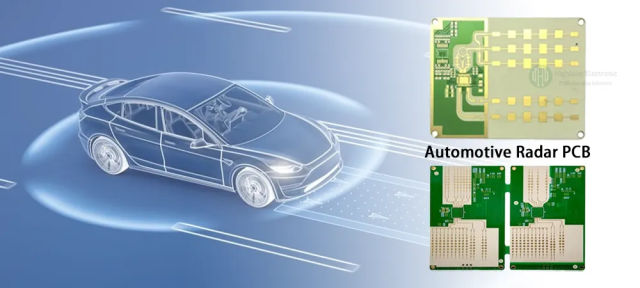
In modern 60 GHz radar sensor modules, used in advanced driver-assistance systems (ADAS), industrial robotics, and short-range imaging, signal integrity and impedance control directly determine detection accuracy and angular resolution.
Even minor inconsistencies in dielectric constant or copper surface roughness can lead to beam distortion, false target reflection, or phase alignment drift, especially across multi-layer RF front-end architectures.
Rogers Duroid 6002 PCB, with a Dk of 2.94 ± 0.04 and Df of 0.0012 @ 10 GHz, has become a preferred substrate for low-loss, high-stability radar front ends. Its ceramic-filled PTFE structure provides excellent thermal dimensional stability (CTE ≈ 24 ppm/°C) and consistent impedance across temperature swings.
However, the transition from prototype to volume production introduces real-world challenges—lamination uniformity, via reliability, and impedance drift—that can compromise the radar’s field accuracy.
KKPCB addresses these through tight dielectric control, multi-frequency impedance calibration, and RF process traceability designed for high-frequency radar systems.
Key Engineering Challenges in Duroid 6002 Radar PCB Fabrication
| Signal Integrity Issue | Root Cause | System Impact |
|---|---|---|
| Impedance drift | Inconsistent resin flow during lamination | RF mismatch, phase imbalance |
| Via inductance variation | Uneven plating or pad stackup | Beamforming distortion |
| Surface roughness loss | Copper grain coarsening | Increased insertion loss |
| Dielectric non-uniformity | Press temperature fluctuation | Frequency-dependent Dk deviation |
KKPCB minimizes these issues through vacuum lamination, controlled resin fill, and inline impedance mapping across the RF layer.
KKPCB’s Signal Integrity Optimization Framework
1. Precision Dielectric & Impedance Control
-
Pre-baking Duroid 6002 cores at 125°C for 4 hrs to remove micro-moisture.
-
Lamination at 190°C / 180 psi / 70 min, with cooling rate ≤ 2°C/min.
-
Achieved dielectric uniformity within ±0.02, ensuring impedance variation ≤ ±4%.
2.Surface Conductor Optimization
-
Utilization of rolled copper (Ra < 0.8 µm) for smoother transmission lines.
-
Insertion loss variation reduced by 18% at 60 GHz compared to standard electro-deposited copper.
3. Inline RF and TDR Calibration
-
-
Impedance scanning with 110 GHz VNA and TDR.
-
Automated data correlation across lot-level production, maintaining phase linearity within 1.2° @ 60 GHz.
-
Case Study — 60 GHz Short-Range Automotive Radar Module
Client: Tier-1 automotive radar manufacturer
Application: 60 GHz SRR (short-range radar) for blind-spot detection and collision avoidance
Stackup: 6-layer hybrid (Duroid 6002 + FR-4) with blind via structure
| Performance Metric | Target | KKPCB Result |
|---|---|---|
| Impedance uniformity | ±5% | ±3.6% measured |
| Insertion loss (S21 @ 60 GHz) | < 0.35 dB/inch | 0.31 dB/inch achieved |
| Phase stability | < 1.5° | 1.1° measured |
| Via reliability | > 99.5% | 99.9% confirmed after 1000 cycles |
Engineering Approach:
KKPCB implemented hybrid stackup simulation to balance CTE between Duroid 6002 and FR-4 layers, minimizing z-axis strain during lamination.
Inline impedance calibration and controlled copper roughness optimization ensured beamforming accuracy and consistent return loss (S11 < –24 dB).
Outcome:
The final radar module achieved a 4.7% detection range improvement and passed AEC-Q200 thermal qualification, demonstrating Duroid 6002’s stability in harsh automotive environments.
Advanced Reliability and Environmental Endurance
| Test Type | Condition | Result |
|---|---|---|
| Thermal cycling | –55°C ↔ +150°C / 1000 cycles | No delamination or impedance shift |
| Humidity resistance | 85°C / 85% RH / 1000 hrs | Df drift < 0.00015 |
| Power stress test | Continuous 8 W/cm² load | Stable loss within ±0.03 dB |
| Mechanical shock | 100 g / 6 ms | No via or trace fracture detected |
KKPCB’s RF validation lab ensures each Duroid 6002 PCB meets stringent automotive reliability standards while preserving millimeter-wave performance consistency.
Engineering Insights — Beyond Loss Tangent Control
While Duroid 6002 provides inherently low dielectric loss, process precision determines its real-world RF stability.
KKPCB integrates 3D EM simulation, TDR calibration, and stackup CTE tuning, bridging the gap between material theory and operational reliability.
For radar engineers, this translates into:
-
Stable impedance and phase control across multilayer stackups.
-
Reduced beam drift in array calibration.
-
Extended operational life under thermal stress.
KKPCB’s Reliability & Traceability Protocol
-
Material lot Dk/Df revalidation under humidity control.
-
3D lamination stress modeling for hybrid radar stackups.
-
Inline 110 GHz impedance mapping and data traceability.
-
Accelerated aging & vibration tests per IPC-TM-650 standards.
-
Failure mode analysis (SEM + cross-section microscopy).
Conclusion — Consistent Signal Integrity, Proven Reliability
Duroid 6002 PCBs provide superior dielectric consistency and low loss for 60 GHz radar sensor modules.
Through KKPCB’s precision impedance control and process-monitored manufacturing, each radar PCB achieves:
-
Stable impedance and phase alignment
-
Repeatable loss performance under temperature stress
-
Verified mechanical and environmental durability
KKPCB’s engineering-driven RF manufacturing ensures measurement accuracy and radar precision for next-generation automotive and industrial systems.
