1. Introduction
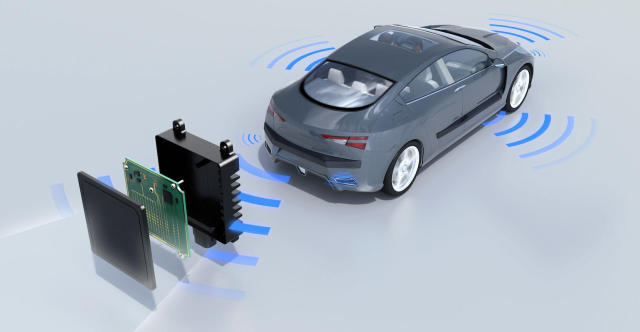
- As the automotive industry races toward higher levels of autonomy, 77 GHz radar systems have become the backbone of advanced driver-assistance systems (ADAS).
At these millimeter-wave frequencies, PCB material stability directly defines radar accuracy, signal phase consistency, and long-term reliability. - Among all high-frequency laminates, Rogers RO4350B PCB has emerged as a proven and cost-effective platform—offering the right balance of low dielectric loss, mechanical stability, and scalable manufacturability for automotive radar modules.

2. Why Choose RO4350B for 77 GHz Radar
- At 77 GHz, even subtle dielectric variations can distort wave propagation and reduce detection accuracy.
RO4350B’s stable dielectric constant (εr = 3.48 ± 0.05) and low dissipation factor (tan δ = 0.0037) ensure consistent signal integrity across a wide temperature range.
| Property | RO4350B Typical Value |
|---|---|
| Dielectric Constant (εr @ 10 GHz) | 3.48 ± 0.05 |
| Dissipation Factor (tan δ @ 10 GHz) | 0.0037 |
| Thermal Coefficient of εr | +50 ppm/°C |
| Glass Transition Temperature (Tg) | > 280 °C |
- Compared with PTFE-based substrates, RO4350B PCBs offer 20–30% lower processing cost and simplified lamination—while maintaining the phase stability and low insertion loss performance needed for high-resolution radar imaging.
3. Real-World Case: European Tier-1 77 GHz Radar Redesign
- A leading European Tier-1 supplier sought to reduce radar PCB cost without compromising RF performance.
They switched from a PTFE-based substrate to a hybrid RO4350B + FR-4 structure, co-developed with KKPCB’s engineering team.
4. Engineering Process & Challenges
During early trials, the customer experienced:
-
Excessive resin flow between layers during lamination
-
Slight phase drift under –40 ~ +125 °C thermal cycling
-
Difficulty maintaining via consistency across dense RF arrays
5. Our Solution
-
Lamination temperature profile to minimize CTE mismatch
-
Controlled resin-flow prepregs to stabilize hybrid interfaces
-
RF test coupon impedance verification for every production lot
6. Results
-
Insertion loss reduced by ~0.15 dB @ 77 GHz
-
Phase consistency improved across 8-layer antenna arrays
-
Hybrid stackup yield increased by 12%
-
Fully qualified under AEC-Q200-equivalent automotive reliability testing
- Engineering Insight:
During validation, we observed that even a 0.05 mm via-drill deviation could shift impedance by > 3%. Through controlled vacuum lamination and ±5 µm etching precision, this issue was completely eliminated.
7. Design and Manufacturing Considerations
- For engineers designing radar front-ends on RO4350B PCB
-
Maintain precise impedance control in microstrip and stripline traces
-
Manage CTE matching in mixed-dielectric stackups
-
Apply vacuum lamination to prevent voids and resin bleed
-
Ensure tight drilling tolerance (±0.05 mm) for stable via geometry
KKPCB’s advanced process control enables:
-
± 5 µm etching accuracy for fine-pitch RF structures
-
Automated impedance tuning with in-line VNA validation
-
Thermal cycling reliability up to +125 °C
-
IATF 16949-compliant process for automotive PCB production
8. Why KKPCB
Unlike conventional PCB suppliers, KKPCB specializes in high-frequency hybrid structures for automotive radar, satellite communication, and RF front-ends.
Our core capabilities include:
-
Engineering co-design support (stackup simulation, material matching)
-
RF impedance modeling & verification via calibrated VNA
-
Hybrid lamination process < ± 3 °C temperature deviation
-
Automotive qualification documentation (PPAP, IMDS, AEC-Q reports)
By integrating design insight and mass-production control, KKPCB helps radar OEMs achieve faster validation cycles, stable performance, and lower overall cost.
9. Conclusion & Engineering Call to Action
- RO4350B PCBs have proven to be a reliable, scalable, and cost-efficient platform for 77 GHz radar systems.
When paired with KKPCB’s process expertise, it becomes a mass-production-ready solution, bridging RF performance with manufacturing reliability. - If you’re developing a 77 GHz radar or mmWave sensor, our engineering team can help you:
-
Optimize hybrid stackups for impedance and thermal balance
-
Validate insertion loss and phase stability via RF testing
-
Accelerate your transition from prototype to automotive-grade mass production
- Contact KKPCB Engineering Support to discuss your next radar PCB project or request a design-for-manufacturing (DFM) review.
