Convection soldering systems remain the primary surface-mount method worldwide, primarily due to their versatility, high efficiency, and excellent heat transfer properties. These properties have become paramount today. The advancement of digitalization, growing production volumes, the diversity of electronic components, and, importantly, the production of printed circuit boards worldwide require efficient and easily configurable production equipment. Therefore, reflow soldering systems are becoming key components of any surface-mount production line. This article examines several important issues related to the configuration of such systems and their impact on the soldering process.
The design of convection solderingequipment allows for relatively easy scaling depending on production requirements. Systems of varying lengths can be designed with different conveyor equipment without altering the fundamental principle of heat transfer. Up to four lines can be combined, with or without central support. The modular design of fixed-size heating and cooling units allows for variable system lengths while ensuring controlled heating.
Nitrogen or air
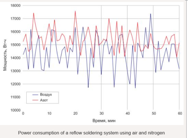
In convection systems, nitrogen or air is typically used as the heat transfer medium. Since air has only slightly higher thermal conductivity than nitrogen, and air is also more viscous, both gases have comparable heat transfer properties. When using reflow soldering, the temperature profile requires only minor or no changes when switching from air to nitrogen and back.
When working with nitrogen, a preset volume of gas (approximately 20 m³/h) is introduced into the system , which heats up along with the already circulating gas flow. In this case, the average energy consumption of the reflow soldering system increases by approximately 0.7 kWh. Nitrogen displaces air and removes oxygen from the working chamber, creating a stable, inert environment that prevents localized oxidation of all materials used in the soldering process.
A comparison of solder reflow samples shows improved wetting and flow in a nitrogen environment. Rehm Thermal Systems reflow soldering systems allow you to set the desired residual oxygen level. This provides the user with an additional parameter that allows them to optimize soldering results to achieve specific PCB characteristics .
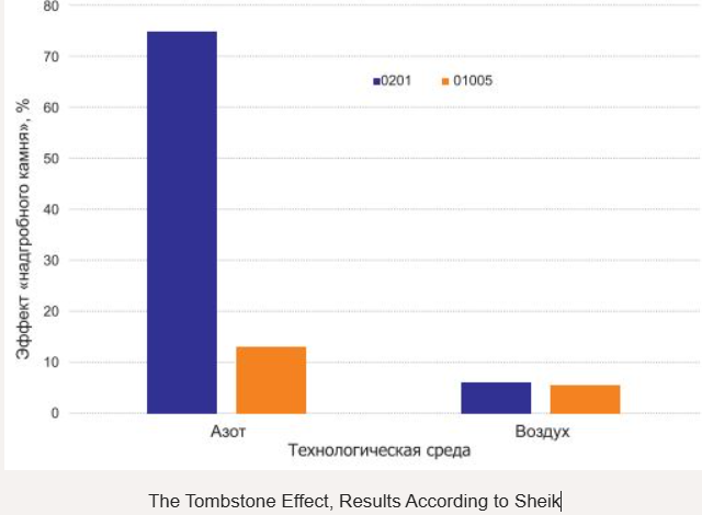
There may be no obvious reason to increase the oxygen concentration in the process chamber, as oxidation degrades wetting properties. However, wetting dynamics can influence the occurrence of certain soldering defects, such as the tombstone effect. The absence of oxygen prevents oxidation and accelerates wetting. This leads to discrepancies in wetting times between the two sides of the component and the formation of the tombstone effect. Therefore, increasing the residual oxygen concentration (e.g., to 500 or 800 ppm ) during reflow soldering can reduce the occurrence of tombstones..
Temperature profile
The goal of temperature profiling is to ensure a reliable connection of all soldered components while preventing them from exceeding their thermal limits. The heating system includes adjustable conveyor speed and blower intensity to achieve the desired temperature-time curve.

Blowing intensity
During reflow soldering, the process fluid becomes a coolant through forced convection. To generate the convection flow, Rehm systems use innovative fans with EC motors. These fans allow the flow to be directly controlled using a built-in frequency controller. The ability to regulate the volumetric flow provides the user with additional control over the temperature-time profile of the printed circuit board (PCB) processing
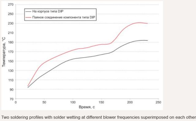
A comparison of two soldering profiles was conducted using the VXP+734, with the blowers operating at different frequency settings. Other parameters, such as conveyor speed and heater temperature settings, remained constant. Clearly, using lower frequencies changes the maximum soldering temperature: the chip component temperature dropped from 241°C to 230°C, and the inductor temperature dropped from 232°C to 217°C.
Fan speed control is rarely considered in practical reflow soldering applications, but this method is well suited for complex applications. For example, this solution is used in Endress + Hauser’s patented backside reflow soldering technology (patent DE 102 11 647 B4). This technology is used for soldering through-the-hole (THD) components, which are particularly sensitive to overheating. Soldering is performed using convection reflow, but the component is positioned on the underside of the board.
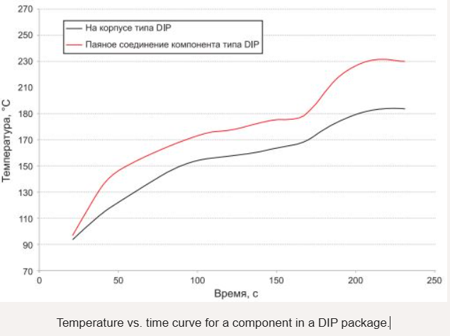
During soldering, heat input to the component body located under the PCB is less intense than to the leads that pass through the board and are soldered on top. The lead of a DIP component heats up to the required soldering temperature of +230°C or higher, while the body temperature located under the PCB remains well below the maximum permissible temperature of +200°C.
This effect is achieved, among other things, by using different frequencies for the fans in the upper and lower modules of the soldering system.
Conveyor speed
Adjusting the heat transfer gas (nitrogen or air) and fan speed allows you to influence the soldering results of printed circuit boards . Furthermore, varying the conveyor speed is another effective way to optimize the temperature-time profile of a reflow soldering system. Even with constant heating zone temperature and fan speed settings, soldering profiles can vary depending on conveyor speed.
Thermal conductivity of the medium during soldering:
| Thermal conductivity W/M k | ||
| Wednesday | +25 °C | +200 °C |
| Air | 0.024 | 0.039 |
| Nitrogen | 0.024 | 0.037 |
As the conveyor speed decreases, the maximum temperature increases at all measurement points, and the temperature difference between the various thermal masses on the PCB decreases. The ambient temperature around the PCB changes only slightly. However, conveyor speed significantly influences heat input to the PCB.
When optimizing a soldering profile, it is strongly recommended to adjust conveyor speed first before adjusting other system parameters. It is important to keep in mind that conveyor speed also affects the occurrence of soldering defects such as solder balls and tombstones.
Trodler [4] was able to demonstrate that using lower conveyor speeds and, correspondingly, longer preheating times reduced the formation of solder balls on the printed circuit board . Wohlrabe [5] was able to reduce the number of tombstones by reducing the speed.
| Advantages of EC motors | |
| Regulation | Built-in frequency controller in each electric motor |
| Noise | Lower than in AC motors |
| Energy consumption | Lower than in AC motors |
| Industry 4.0 | Direct interface for > 27 data |
| Preventive maintenance | Continuous monitoring of important operating parameters |
CoolFlow Method
The previously described methods for creating an inert environment in the soldering zone and adjusting temperature-time curves have been known for a long time. However, the simultaneous use of liquid nitrogen as a coolant and inert process environment represents an innovative approach.
With the CoolFlow method, the company is the first to implement a concept developed by Air Liquide GmbH (EP 2 771 145 B1) in machine technologies.
This method completely eliminates water as a coolant, which was previously widely used in reflow soldering systems. Cooling in these systems is accomplished with liquid nitrogen, which then condenses into a gas, creating an inert environment in the process chamber. Eliminating water cooling significantly reduces energy costs. Using CoolFlow technology, the VXP+ soldering system consumes 10 kWh or less
in operating mode under real-world production
conditions . CoolFlow technology also enables the setting of steep cooling gradients, for example to reduce cooling times, and also allows for the adjustment of cooling gradients down to –6 K/s.
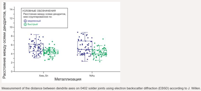
In their research, Willen [3] and Grosinger [2] examined in some detail the effect of steep cooling gradients on the reliability of solder joints. Measuring the distances between dendrite axes using electron backscatter diffraction (EBSD) on 0402 components on nickel-gold and indium-tin-plated printed circuit boards, Willen found only a slight tendency for rapid cooling to refine the grain size of solder joints. When examining the scattering range, the cooling gradient and the printed circuit board coating did not have a significant effect on the microstructure of the solder joints.
Subsequent shear force measurements conducted by Grosinger after testing at successive temperature gradients (–40/+125°C) confirmed the metallurgical results. They showed that a cooling gradient in the generally accepted range for reflow soldering of up to –6 K/s does not significantly impact the reliability of the soldered joints. After 250, 500, and 1000 cycles, the shear force reduction is observed within the same range at different cooling gradients for the CR1206 and LED components. Thus, CoolFlow technology offers users significantly more flexibility, especially when soldering very large PCBs .

This article examines a number of important issues related to the configuration of convection soldering systems and their impact on the soldering process.
Reflow soldering systems offer a wide range of system parameters, allowing the process to be tailored to a wide range of requirements. The combination of proven solutions and innovative technologies, such as EC or CoolFlow motors, not only improves manufacturing processes but also lays the foundation for creating machines that meet Industry 4.0 requirements.
Reflow soldering systems are an integral part of every surface-mount assembly production line . This article answers some important questions related to the configuration of these systems and their impact on the soldering process.
KKPCB is your trusted one-stop partner for full-cycle PCB and PCBA solutions. We handle every stage of your project, from PCB design and prototype verification to precision manufacturing, SMT & DIP assembly, testing, and global packaging. By providing your Gerber files or specifications, our experienced team delivers high-quality, reliable PCBs and fully assembled PCBA products tailored to your needs. With advanced equipment, strict quality control, and a customer-focused approach, KKPCB serves industries worldwide, including industrial control, automotive electronics, IoT devices, telecommunications, and consumer electronics, helping clients streamline production, reduce risk, and accelerate time-to-market.
