Robotics PCB Engineering for High-Precision Autonomous and Industrial Robot Systems
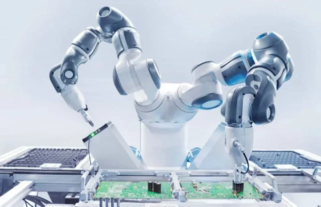
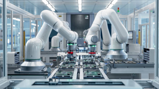
Robotics has evolved into a domain where mechanical precision is useless without equally precise electronics. At the center of every actuator, servo, sensor array, and AI-driven perception engine sits a Robotics PCB—a board engineered to survive vibration, deliver deterministic control, maintain signal integrity, and integrate diverse sensing pathways. A Robotics PCB is not a generic board; it is a high-performance platform combining real-time computing, motor-drive control, power management, and environmental robustness.
A strong Robotics PCB design underpins stability, accuracy, and responsiveness across autonomous mobile robots (AMRs), industrial manipulators, collaborative robots (cobots), surgical robots, and high-speed inspection machines.
1. High-Frequency Signal Integrity for Deterministic Motor Control
Robots depend on precise PWM (pulse-width modulation) signals, encoder feedback, and closed-loop control systems. Any signal distortion in the Robotics PCB can propagate as jitter, torque ripple, or positional error.
A performance-optimized Robotics PCB focuses on:
• Controlled-impedance traces for encoder channels and high-speed control buses
• Differential routing for noise-sensitive feedback lines (Hall sensors, optical encoders)
• Low-loss laminates where high switching frequencies exceed 200 kHz
• Ground-referenced return paths to eliminate phase drift in control loops
Robotics PCB architectures must maintain microsecond-level timing accuracy even when power stages generate aggressive switching noise. This stability directly affects motion smoothness, repeatability, and robot safety.
2. Power Distribution and High-Current Path Engineering
Robots draw sharp bursts of current during acceleration, load carrying, and torque compensation. A Robotics PCB must support these dynamic loads with minimal voltage sag.
Key design requirements:
• Thick copper planes for high-current motor phases and servo power rails
• Low-impedance power distribution networks (PDN) to stabilize microcontrollers and DSPs
• Thermal-balanced copper geometries to avoid localized hotspots
• Synchronous rectification and high-efficiency DC-DC stages for battery-powered robots
In robotics, PDN performance is directly tied to actuator responsiveness. Weak power distribution produces unstable trajectories and overheating—both catastrophic for industrial environments.
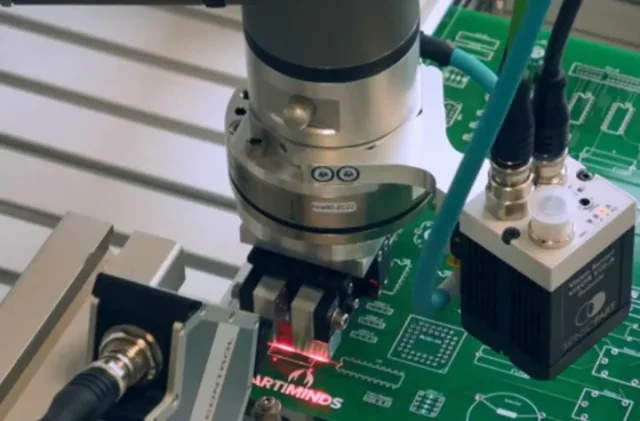
3. Sensor Fusion and Multi-Modal Integration on Robotics PCB
Modern robots rely on extensive sensor suites: IMUs, LiDAR, ToF sensors, tactile arrays, force–torque sensors, ultrasound modules, and machine-vision engines. A Robotics PCB must route these heterogeneous signals while maintaining low noise floors.
Critical techniques include:
• Isolated sensor domains separating analog precision circuits from digital noise
• Shielded zones for low-voltage analog sensing
• High-speed MIPI and USB differential routing for vision modules
• Synchronized sampling circuits to reduce temporal skew in sensor fusion
A well-designed Robotics PCB enhances perception accuracy and enables consistent environmental mapping—a core requirement for autonomous navigation and manipulation.
4. Mechanical Robustness and Vibration-Resistant PCB Structures
Robots vibrate, twist, accelerate, and occasionally collide. A Robotics PCB must tolerate harsh mechanical stress without trace fatigue or solder-joint cracking.
Stability is achieved through:
• Reinforced stackups and thicker FR-4 or hybrid laminates
• Heavy copper anchors for connectors and motor driver modules
• Underfill and corner-bonding for BGA-mounted AI or MCU processors
• Flex-rigid Robotics PCB architecture for moving joints and rotating axes
Mechanical robustness is absolutely non-negotiable when robotics electronics operate in high-cycle industrial tasks.
5. Thermal Management for Motor Drivers and AI Compute Modules
Robotics PCBs often host high-power MOSFETs, gate drivers, and on-board AI accelerators. Heat management determines long-term reliability.
Effective thermal solutions include:
• Thermal vias under driver packages
• Copper heat spreading zones
• Metal-based PCB substructures for high-load motor stages
• Hybrid stackups using ceramics or PTFE materials for low thermal resistance
High thermal stability within Robotics PCB designs ensures consistent torque output, prevents derating, and preserves embedded computing performance.
6. EMI/EMC Compliance for Multi-Motor and Multi-Sensor Systems
Robots have dense electrical ecosystems: stepper drivers, brushless motors, switching regulators, Ethernet, Wi-Fi, and sensitive analog sensors. Without EMI control, the entire system becomes unstable.
Successful EMI control in Robotics PCB design requires:
• Dedicated return paths minimizing loop area
• Ground partitioning for motor and logic domains
• LC filtering on phase outputs and sensor inputs
• Shielded enclosures integrated with the PCB ground plane
Precision robots demand electromagnetic discipline; even minor interference can misalign positioning or corrupt sensor data.
Conclusion
A Robotics PCB is a complex engineering backbone that blends motion control, sensing, power management, computing, and structural resilience. As robots evolve into more autonomous, collaborative, and intelligent systems, Robotics PCB design becomes increasingly mission-critical. High signal integrity, robust thermal engineering, EMI suppression, and sensor-rich architecture allow next-generation robots to perform accurately, safely, and efficiently across industrial and commercial landscapes.
The deeper the PCB engineering, the more capable the robot.
