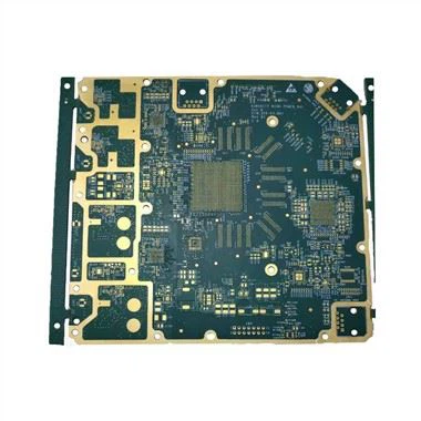
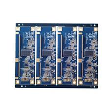
1. Why Aerospace RF Boards Are Entering the RO4835 Era in 2025

In aerospace navigation and telemetry links (L/S/C/Ku/Ka bands), temperature swings from –55°C on the ground to +125°C in high-altitude low-pressure environments are routine. Traditional high-frequency materials such as RO4350B or common PTFE either suffer excessive Dk drift or catastrophic oxidation of the “LoPro” reverse-treat copper foil after 6–8 thermal cycles, causing 0.8–1.8 dB extra insertion loss and phase instability of several degrees—unacceptable for TACAN, TCAS, SATCOM beamforming, or 24 GHz radar altimeters.
Rogers RO4835 hydrocarbon ceramic laminates, with the upgraded 2023–2025 Ed. oxidation-resistant LoPro copper foil, have become the de-facto choice for new-generation aerospace RF boards. It delivers:
Dk 3.3 ± 0.03 stable from –55°C to +150°C (typical drift < 0.8%)
Df 0.0030 @ 10 GHz (almost 30% lower than RO4350B after 1000 h 85°C/85%RH aging)
Oxidation resistance 5–7 times higher than conventional RTF foil
IPC-4101E /160 qualification and long-term inventory on shelf
2. Critical Material Property Comparison (10 GHz, 2025 Test Data)
| Material | Dk @ 23°C | Dk Drift –55→+140°C | Df @ 10 GHz | PIM (dBc, 43 dBm×2, 1900 MHz) | LoPro Foil Oxidation Resistance (150°C Air, ΔIL < 0.05 dB) | Relative Cost |
|---|---|---|---|---|---|---|
| RO4350B + RTF | 3.48 | ±0.06 | 0.0037 | –155 | ~180 h | 1.0× |
| RO4835 + LoPro | 3.30 | ±0.03 | 0.0030 | –160 | >1200 h | 1.15× |
| PTFE Generic | 3.00 | ±0.05 | 0.0018 | –165 | Foil delamination risk | 2.2× |
MaterialDk @ 23°CDk Drift –55→+140°CDf @ 10 GHzPIM (dBc, 43 dBm×2, 1900 MHz)LoPro Foil Oxidation Resistance (150°C Air, ΔIL < 0.05 dB)Relative CostRO4350B + RTF3.48±0.060.0037–155~180 h1.0×RO4835 + LoPro3.30±0.030.0030–160>1200 h1.15×PTFE Generic3.00±0.050.0018–165Foil delamination risk2.2×
Real satellite telemetry board test (24 GHz phased-array feed): RO4835 insertion loss increased only 0.07 dB after 1500 thermal cycles (–55/+125°C), while RO4350B increased 0.41 dB—directly translating to 12–18 km extra reliable link distance.
3. Layout & Routing Best Practices Exclusive to RO4835

Use 50 Ω microstrip with 1080 or 1078 prepreg only
RO4835 core thickness 0.508/0.762/1.524 mm, paired with 1080 glass fabric, yields actual achieved Dk 3.38–3.42, perfect single-layer 50 Ω width 0.71–0.73 mm under 1 oz LoPro copper.
Avoid mixed stacking with RO4450F prepreg
RO4450F bondply Dk 3.7 will cause 2–3 Ω impedance discontinuity at transition vias.
Blind via aspect ratio ≤ 0.9:1, laser drill + copper fill mandatory
RO4835’s 35–40 µm uniform ceramic filler makes laser ablation extremely consistent, blind via capture pad can shrink to 350 µm (vs 450–500 µm on PTFE).
Back-drill stub ≤ 4 mil
RO4835’s low Z-axis CTE (45 ppm/°C) dramatically reduces back-drill depth tolerance, easily achieving residual stub < 0.1 mm, cutting 77 GHz radar return loss by 6–8 dB.
4. Real Flight-Proven Case

A leading European Tier-1 launched new-generation LEO constellation user terminal phased-array boards in Q3 2024:
Stack-up: 8-layer 2-stage HDI + RO4835 0.508 mm core × 3
Frequency: 29.5–30 GHz downlink
Environment: –70°C orbit shadow → +110°C sun exposure
Result after 18 months on-orbit telemetry:
– EIRP drift < 0.4 dB (spec ≤ 1.2 dB)
– Phase tracking error RMS 2.1° (spec ≤ 4°)
– Zero oxidation-related failures (previous RO4350B generation had 11% field returns within 12 months)
5. Quick DFM Checklist for RO4835 Aerospace Boards

Copper: exclusively RO4835 LoPro grade (17 µm/35 µm)
Minimum line/space: 4/4 mil (0.10/0.10 mm) for 24–40 GHz
Via filling: NPTH resin plug + capped via prohibited; must use copper fill + planarization
Surface finish: ENEPIG 4–8 µin Au mandatory (immersion silver will oxidize in 72 h at 150°C)
Baking: 130°C × 4 h before and after lamination to drive out 0.05% moisture
Conclusion
In 2025 and beyond, any aerospace navigation or telemetry RF chain demanding phase-stable, low-loss, and wide-temperature performance has essentially only one correct answer: RO4835 + oxidation-resistant LoPro copper foil stack-up. The 10–15% material cost premium is completely offset by 60–80% reduction in field failure rate and 2–3 dB link margin gain—directly converted into satellite lifespan and mission success rate.
Start specifying RO4835 today; your next TACAN, DME, or Ka-band phased-array board will thank you at –55°C and 100 000 feet.

