How Defense PCBs Secure Critical Military Systems
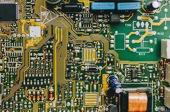
In modern defense technology, where milliseconds determine mission success and electronic failure can compromise national security, Defense PCBs stand as the silent guardians that ensure military systems operate flawlessly. More than simple circuit carriers, these boards are engineered to perform under extreme heat, rapid pressure shifts, electromagnetic attacks, and violent shock events—conditions far beyond the limits of commercial electronics.
This enhanced technical guide explores the engineering principles, materials, components, security mechanisms, and manufacturing challenges behind Defense-Grade PCBs, providing a clear understanding of why they remain indispensable to mission-critical military systems.
1. Why Defense PCBs Are the Backbone of Military Technology
Military systems—whether airborne, underwater, or on the battlefield—rely on a vast network of electronic subsystems:
-
Secure tactical communication
-
Radar and long-range surveillance
-
Electronic warfare (EW)
-
Navigation and guidance
-
Missile control and smart weapon systems
-
Autonomous unmanned platforms (UAVs/UGVs/USVs)
Unlike consumer PCBs, defense PCBs are engineered for absolute reliability:
1.Extreme temperature resilience
Operating from -55°C to +150°C with minimal dielectric drift.
2.Shock & vibration resistance
Meeting MIL-STD-810 and MIL-PRF-31032 durability standards.
3.Radiation & EMI immunity
Using hardened ICs, shielding, and ground isolation to ensure stable operation even in high-EMI environments.
4.Secure architecture
Anti-tamper layouts, encrypted firmware, and secure material traceability.
A single failure in these boards could impact a mission, an aircraft, or even national defense—making engineering precision paramount.
2. Key Application Areas of Defense PCBs
Defense PCBs are deployed widely across mission platforms:
2.1 Secure Military Communications
-
Encrypted RF transceivers
-
Satellite communication (SATCOM)
-
Tactical radios & battlefield network devices
High-frequency PCBs using Rogers, Taconic, Arlon, or ceramic laminates minimize loss and ensure accurate 50-ohm transmission line performance.
2.2 Radar & Surveillance Systems
Modern radar systems depend on PCBs capable of handling >10 GHz microwave and >30 GHz millimeter-wave signals.
Requirements include:
-
Ultra-low Df substrates for minimal insertion loss
-
Tight impedance control (±5%)
-
High-density phased-array antenna integration
These systems cannot tolerate even slight signal distortion.
2.3 Weapon Systems & Precision-Guided Munitions
PCBs in missile guidance, fuzes, and targeting systems must endure:
-
Extreme G-forces
-
Rapid accelerations
-
Thermal shocks
-
High vibration
Boards adopt HDI, microvia structures, ceramic substrates, and redundant paths for guaranteed function.
2.4 Unmanned Systems (UAV / UGV / USV)
Defense drones require lightweight yet thermally stable PCBs to support:
-
Flight control
-
Data links
-
Onboard processing
-
Sensor fusion modules
These use polyimide, PTFE, and hybrid stackups to maintain signal integrity at high altitudes and low temperatures.
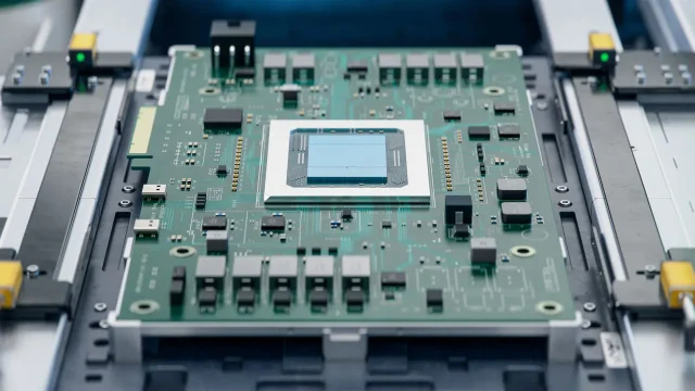
3. Military-Grade Components: Built for Survival
Military PCB components are not typical commercial parts—they meet MIL-PRF-based qualifications and include:
• Extended-range resistors & capacitors
Operating from -55°C to 125°C with ppm-level stability.
• Ruggedized connectors
Vibration-proof, secure mating, sealed against dust & moisture.
• Radiation-hardened ICs
Protecting against EMI, EMP, and cosmic radiation.
• Thermal management structures
Heat sinks, metal cores, thermal vias, and copper coins optimize dissipation.
Each component must pass:
-
Burn-in testing
-
Thermal cycling
-
Salt-fog exposure
-
Random vibration testing
Ensuring absolute reliability under combat conditions.
4. Secure PCB Design: Protecting Military Electronics
Security in defense PCBs extends beyond physical ruggedness—it also includes cyber and anti-tamper protections.
4.1 Anti-Tamper & IP Protection
Defense PCBs often integrate:
-
Encrypted bootloaders
-
Secure microcontrollers
-
Embedded authentication keys
-
Layer-embedded data paths
-
Anti-reverse-engineering obfuscation
These measures help prevent unauthorized duplication or intelligence leakage.
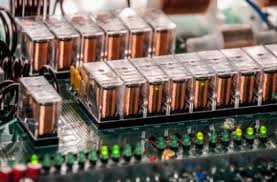
4.2 EMI/EMC Hardening
Battlefield electronics face severe electromagnetic threats.
Defense PCBs implement:
-
Ground isolation zones
-
Shielding cans
-
Faraday structures
-
Dedicated EMI layers
-
Controlled return paths
Noise levels can be reduced by up to 30% with optimized multilayer grounding.
4.3 Supply Chain Security
Approved suppliers prevent counterfeit components from entering critical systems. This is essential for:
-
Traceability
-
Cybersecurity
-
Reliability assurance
Defense electronics require 100% verified material origin.
5. Manufacturing Challenges Unique to Defense PCBs
Producing military-grade PCBs demands advanced engineering and rigorous controls.
Harsh-Environment Testing
Including:
-
Thermal shock: -65°C ↔ 150°C
-
High-humidity endurance
-
Vibration & drop testing
-
Salt-spray corrosion tests
Compliance with MIL & IPC Standards
Key standards include:
-
MIL-PRF-31032 (Printed Boards)
-
MIL-STD-883 (Microcircuits Testing)
-
IPC-6012 Class 3 / 3A
-
AS9100D for aerospace-grade quality
High Material Costs
High-frequency materials can cost 5–10× more than FR-4, and require specialized equipment.
Long Lead Times
Due to custom stackups, testing, and component screening.
This is why only highly specialized PCB manufacturers can support defense programs.
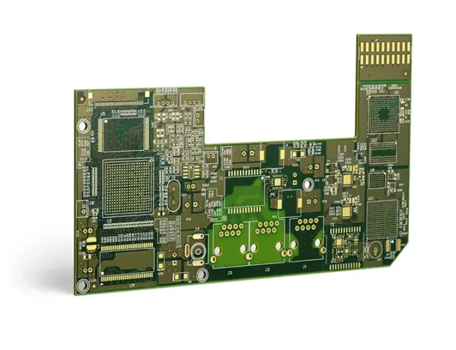
6. Critical System PCBs: Zero-Failure Architecture
Critical system PCBs power operations where failure equals catastrophe.
Examples:
-
Missile guidance processors
-
Fighter jet avionics
-
Nuclear command communication
-
Emergency battlefield communication systems
Engineering principles include:
-
Redundant circuit paths
-
Fault isolation zones
-
10+ Gbps controlled-impedance routing
-
Accelerated life testing
-
Thermal & mechanical fail-safe protection
These boards are designed to last 10–20 years in demanding deployments.
7. Future Trends in Defense PCB Technology
Defense PCB innovation continues evolving:
(1) Miniaturization + Higher Density
HDI, microvias, and stacked vias for next-gen compact systems.
(2) Advanced Substrates
Ceramics, PTFE, and IMS for extreme thermal environments.
(3) Enhanced Cybersecurity
Integrated hardware encryption and tamper-proof design.
(4) Additive Manufacturing
3D-printed PCBs for faster prototyping and complex geometries.
(5) AI-Driven PCB Diagnostics
Predictive failure analytics for long-term reliability.
The future battlefield will rely even more on sophisticated and secure PCB architectures.
8. Selecting the Right Defense PCB Partner
A qualified defense PCB manufacturer should offer:
-
AS9100D / MIL-Q-9858-certified processes
-
Secure & traceable supply chain
-
High-frequency material expertise
-
Full environmental testing capability
-
Strict confidentiality & secure data handling
-
Precision fabrication for HDI & hybrid stackups
Choosing the right partner directly determines mission reliability.
Conclusion: The Silent Guardians of Modern Warfare
Defense PCBs are more than components—they are the core stability and security layer of critical military systems.
From radar arrays to guided weapons and tactical communications, these boards operate in silence, ensuring mission success where failure is not an option.
As threats evolve and technology accelerates, defense PCBs will continue to advance—stronger, faster, more secure—to safeguard the future of global defense.
