Engineering Context
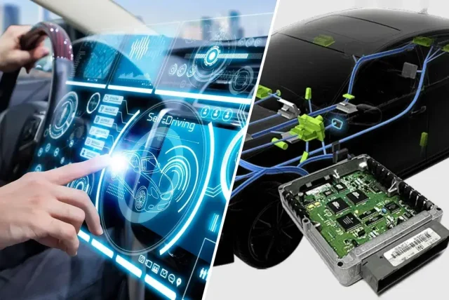
Modern automotive electronics platforms are rapidly evolving toward higher levels of autonomy, requiring seamless integration of radar sensors, cameras, LiDAR modules, GNSS receivers, and centralized computing architectures. At the heart of these systems lies the Automotive Electronics PCB, which serves as the critical interconnection platform for high-frequency RF signals, high-speed digital interfaces, and power management circuits.
Automotive radar systems operating at 76–81 GHz demand exceptional phase consistency and low-loss RF performance. Small variations in dielectric properties, copper roughness, or layer alignment can introduce phase errors that directly affect target detection accuracy, object classification, and sensor fusion algorithms. As ADAS and autonomous driving systems increasingly rely on synchronized sensor inputs, PCB-induced signal degradation becomes a major engineering concern.
To address these challenges, KKCPB employs advanced RF PCB design methodologies, controlled impedance structures, precision lamination technologies, and simulation-driven validation workflows. Through optimized stackup architecture and manufacturing process control, Automotive Electronics PCBs can achieve stable phase behavior, reduced insertion loss, and reliable operation under harsh automotive environments.
This article examines the engineering principles behind phase-stable automotive radar PCBs and presents a real-world KKCPB case study involving a sensor fusion platform developed for next-generation autonomous driving applications.
Core Engineering Challenges
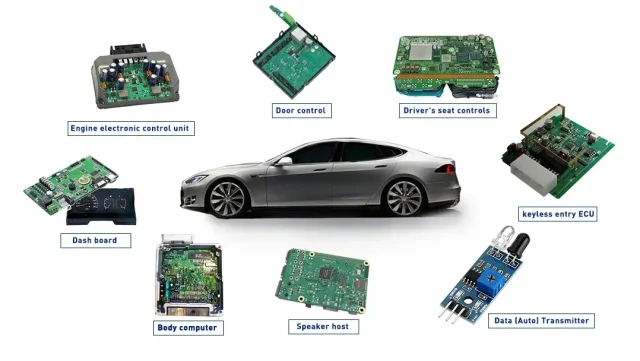
Automotive radar and sensor fusion systems combine multiple RF channels, high-speed digital networks, and power electronics within compact electronic control units. Several critical engineering challenges must be addressed.
| Challenge | Root Cause | Engineering Impact |
|---|---|---|
| Phase inconsistency between radar channels | Dielectric variation and stackup asymmetry | Reduced radar resolution and beamforming accuracy |
| High insertion loss at 77 GHz | Copper surface roughness and dielectric dissipation | Reduced detection range and signal quality |
| EMI coupling between RF and digital circuits | Dense routing and inadequate isolation | Sensor interference and false target detection |
| Thermal drift during operation | Continuous power dissipation in radar processors | Frequency instability and calibration errors |
| Mechanical stress from vehicle operation | Vibration and thermal expansion cycles | Impedance variation and solder fatigue |
These challenges directly influence radar sensitivity, object tracking precision, and long-term reliability of ADAS platforms.
Material Science & Dielectric Performance
Automotive radar systems require PCB materials capable of maintaining dielectric consistency across wide temperature ranges while supporting low-loss RF transmission.
For sensor fusion platforms, material selection is often driven by requirements related to phase stability, insertion loss, moisture resistance, and manufacturability.
Automotive Electronics PCB Material Characteristics
| Parameter | Typical Value | Engineering Benefit |
|---|---|---|
| Dielectric Constant Stability | ±0.05 | Maintains impedance consistency |
| Dissipation Factor | <0.003 | Reduces RF insertion loss |
| Thermal Conductivity | 0.8–1.5 W/m·K | Improves heat dissipation |
| CTE (X/Y) | 10–15 ppm/°C | Minimizes thermal-induced distortion |
| Moisture Absorption | <0.1% | Preserves dielectric stability |
| Reflow Resistance | >260°C | Supports automotive assembly processes |
Low dielectric loss becomes increasingly important at mmWave frequencies. A small increase in dissipation factor can significantly affect insertion loss, reducing radar detection capability and increasing calibration complexity.
For automotive electronics procurement teams, stable dielectric performance translates into higher production consistency, lower rejection rates, and predictable field reliability.
KKCPB Case Study — Automotive Radar PCB for Sensor Fusion Controller
Client & Application Context
A global Tier-1 automotive electronics supplier approached KKCPB for the development of an Automotive Electronics PCB used in a centralized sensor fusion controller. The platform integrated:
- 77 GHz radar modules
- Multi-camera interfaces
- Gigabit Ethernet communication
- ADAS processing units
- Vehicle domain controller connectivity
The project required exceptional phase consistency across multiple radar channels while maintaining low insertion loss and EMI immunity.
Engineering Problem
The customer’s previous design suffered from several issues:
- Radar phase mismatch exceeding 1.9°
- RF channel insertion loss approaching 0.45 dB/in
- Crosstalk between radar and high-speed Ethernet traces
- Thermal drift during prolonged operation
- Excessive calibration time during production testing
These issues negatively affected target tracking accuracy and increased manufacturing costs.
KKCPB Engineering Solution
The KKCPB engineering team implemented a comprehensive optimization strategy:
- Controlled impedance RF routing throughout the radar signal chain
- Hybrid RF stackup incorporating low-loss dielectric layers
- Ground plane segmentation for RF and digital isolation
- Low-profile copper treatment to reduce conductor loss
- Embedded TDR verification structures
- Differential pair optimization for Ethernet communication
- Thermal balancing around radar transceiver devices
Measured Results
| Parameter | Target | KKCPB Result |
|---|---|---|
| Impedance Variation | ±5% | ±1.6% |
| Phase Deviation | <1° | 0.48° |
| Insertion Loss @ 77 GHz | <0.35 dB/in | 0.27 dB/in |
| Return Loss (S11) | < -15 dB | -19.1 dB |
| EMI Noise Reduction | Baseline | 32% Improvement |
| Radar Calibration Time | <15 min | 8 min |
Outcome
The optimized Automotive Electronics PCB achieved stable radar phase alignment across all RF channels and significantly improved sensor fusion performance. Reduced insertion loss enhanced radar detection range, while improved EMI suppression minimized communication errors between radar and processing subsystems.
The customer successfully deployed the platform into pilot autonomous vehicle programs, achieving improved production yield and reduced calibration costs.
Stackup Design & RF Implementation
The stackup architecture was developed to balance RF performance, thermal stability, and manufacturability.
Hybrid 8-Layer Automotive Radar Stackup
| Layer | Function | Material |
|---|---|---|
| L1 | Radar RF Signal | Low-Loss RF Laminate |
| L2 | Ground Plane | Copper |
| L3 | High-Speed Signal | High-Tg Material |
| L4 | Power Plane | High-Tg Material |
| L5 | Sensor Interface Signal | High-Tg Material |
| L6 | Ground Plane | Copper |
| L7 | RF Routing Layer | Low-Loss RF Laminate |
| L8 | Bottom Control Layer | High-Tg Material |
Simulation & Validation
The design underwent extensive simulation and verification before production.
HFSS Simulation
- Radar antenna feed optimization
- RF transmission path validation
- Crosstalk reduction analysis
ADS Verification
- S-parameter analysis
- Insertion loss modeling
- Phase consistency optimization
TDR Testing
- Controlled impedance verification
- Reflection analysis
- Manufacturing tolerance validation
Thermal FEM Analysis
- Radar transceiver hotspot prediction
- Heat spreading optimization
- Thermal drift evaluation
Simulation results showed excellent correlation with measured production data, validating the effectiveness of the RF implementation strategy.
Environmental& Reliability Validation
Automotive electronics must withstand harsh operating conditions throughout the vehicle lifecycle.
| Test | Condition | Result |
|---|---|---|
| Thermal Cycling | -40°C to +125°C, 1000 cycles | No delamination |
| High Temperature Storage | 150°C, 1000 h | Stable dielectric performance |
| Humidity Test | 85°C / 85% RH, 1000 h | Dk variation <0.02 |
| Mechanical Vibration | 5–500 Hz, 10G | No solder cracking |
| Mechanical Shock | 50G Pulse | No PCB damage |
| Solder Reflow | 260°C ×3 cycles | No warpage >0.08 mm |
| EMI Validation | Full System Test | Crosstalk reduced 32% |
Testing confirmed that the Automotive Electronics PCB maintained phase stability and RF performance throughout automotive qualification conditions.
Engineering Summary
Automotive radar and sensor fusion platforms require PCB technologies capable of delivering low-loss RF transmission, stable impedance control, and long-term phase consistency. As radar frequencies continue to move into the mmWave range and autonomous driving systems become more sophisticated, PCB design and manufacturing quality increasingly determine system performance.
KKCPB combines RF simulation, precision stackup engineering, controlled impedance manufacturing, and comprehensive validation testing to support advanced Automotive Electronics PCB applications. Through optimized material selection, EMI mitigation strategies, and process-controlled fabrication, KKCPB helps automotive OEMs and Tier-1 suppliers achieve reliable radar performance, improved sensor fusion accuracy, and scalable manufacturing consistency.
For automotive radar, ADAS, autonomous driving, and sensor fusion PCB projects, contact the KKCPB Engineering Team to discuss RF stackup optimization, prototype development, and volume production solutions tailored to your application requirements.
