1. Engineering Overview / Abstract
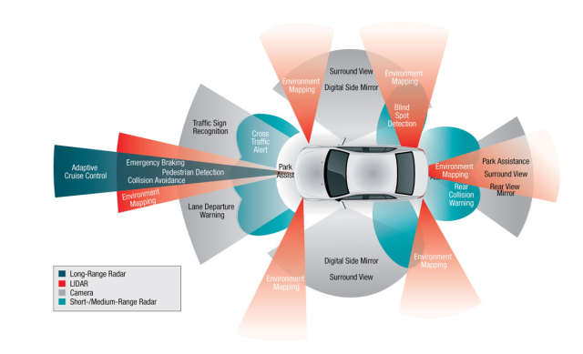
Automotive radar technology operating in the 76–81 GHz band demands printed circuit boards with extremely low dielectric loss, phase stability, and high thermal endurance.
Taconic TLY-5 PCB laminates—featuring a Dk of 2.20 ± 0.02 and Df of 0.0009 @ 10 GHz—offer a robust foundation for mmWave antenna arrays, signal distribution, and transceiver interconnects.
Through KKPCB’s precision lamination control, hybrid stackup optimization, and high-frequency simulation alignment, engineers achieved both low insertion loss and thermal mechanical stability, ensuring radar signal consistency even under wide ambient temperature ranges (–40 °C to +150 °C).
2. Technical Challenges in Automotive Radar PCB Design
| Challenge | Root Cause | System Impact |
|---|---|---|
| Dielectric loss at mmWave | Inconsistent substrate Dk / rough copper | Reduces signal gain and radar detection distance |
| Phase shift with temperature | PTFE expansion mismatch | Degrades angular resolution |
| Heat buildup near PA circuits | Localized thermal hotspots | Alters impedance and system calibration |
These challenges necessitate materials combining ultra-low loss and thermal uniformity, with reliable via metallization and layer adhesion over high-temperature cycles.
3. Material Science: Taconic TLY-5 Substrate Properties
| Parameter | Typical Value | Engineering Benefit |
|---|---|---|
| Dielectric Constant (Dk) | 2.20 ± 0.02 @ 10 GHz | Stable impedance and phase control |
| Dissipation Factor (Df) | 0.0009 @ 10 GHz | Low insertion loss at 77 GHz |
| CTE (Z-axis) | 160 ppm/°C | Controlled warpage and via integrity |
| Thermal Conductivity | 0.25 W/m·K | Enhanced heat dissipation from PA circuits |
| Moisture Absorption | < 0.02 % | Reliable radar calibration in humid climates |
Compared with ceramic-filled PTFE materials, TLY-5 maintains flexibility for multilayer build-up while retaining low loss comparable to pure PTFE systems.
4. KKPCB Case Study — 77 GHz Automotive Radar Module
Project Objective
Improve mmWave antenna performance and long-term reliability for radar modules mounted near engine compartments.
Design Approach
-
4-layer hybrid stackup: TLY-5 (0.254 mm core) + FR-408 HR prepreg for mechanical reinforcement
-
Rolled copper foil (Ra < 1.0 µm) to minimize conductor loss
-
Vacuum lamination + plasma desmear to improve PTFE-to-FR4 adhesion
-
Embedded thermal vias for localized PA heat evacuation
Measured Results
| Performance Parameter | Target | KKPCB Result |
|---|---|---|
| Insertion Loss (77 GHz, 50 mm trace) | < 1.0 dB | 0.86 dB |
| Phase Shift (–40 °C to +125 °C) | < 5° | 3.2° |
| Return Loss (S11) | < –15 dB | –18.6 dB |
| Warpage (after 3× 260 °C reflow) | < 0.15 mm | 0.09 mm |
Outcome:
The optimized TLY-5 radar board maintained consistent signal gain and beam accuracy after 1000 thermal cycles, outperforming standard FR-4/PTFE mixed laminates.
5. Design Optimization & Stackup Strategy
Stackup Structure
-
Layer 1: Antenna array (TLY-5 core, 0.254 mm)
-
Layer 2: Ground plane (rolled copper foil)
-
Layer 3: Power and control routing (FR-408 HR)
-
Layer 4: Shield / base copper
Simulation Verification
-
HFSS modeling: 77 GHz transmission line insertion-loss improvement by 0.18 dB/inch
-
TDR analysis: Impedance deviation within ± 3 Ω
-
Thermal FEA: Peak hotspot temperature reduced by 9 °C due to thermal via optimization
6. Environmental and Reliability Testing
| Test | Condition | Result |
|---|---|---|
| Thermal Shock | –55 °C ↔ +150 °C, 1000 cycles | No delamination or via cracking |
| Humidity Resistance | 85 °C / 85 % RH, 1000 h | ΔDf < 0.0001 |
| Solder Reflow | 260 °C × 3 cycles | No substrate deformation |
| Vibration | 5 – 500 Hz, 3 axes | No resonance drift |
7. Conclusion
Taconic TLY-5 PCB substrates enable low-loss, thermally reliable radar board designs that meet the stringent demands of automotive 77 GHz mmWave radar.
Through KKPCB’s hybrid stackup engineering, controlled lamination, and signal-thermal co-simulation, designers can achieve consistent phase accuracy, low EMI emission, and durable interconnect reliability in real-world driving conditions.
8. Contact / CTA
For customized automotive radar PCB stackups, simulation support, and mmWave material validation, contact the KKPCB RF Engineering Team.
KKPCB provides impedance-controlled, reliability-tested PCB solutions optimized for radar, communication, and sensor applications.
