1. Engineering Overview / Abstract
As 5G smartphone antenna modules integrate multiple MIMO paths and beam-forming arrays, precise impedance control and thermal uniformity become critical for stable signal transmission.
Taconic RF-35 PCB substrates enable consistent dielectric performance and low-loss propagation under compact, multilayer conditions.
KKPCB engineers apply fine-tuned lamination and impedance verification processes to maintain phase coherence and low insertion loss across high-density 5G antenna feed networks.
2. Engineering Context & Technical Challenges
5G smartphone antenna modules combine RF front-end filters, power amplifiers, and antenna arrays within a tight thermal enclosure.
At frequencies up to 39 GHz, minor variations in dielectric or copper roughness can cause impedance mismatch and heat-induced detuning.
| Engineering Challenge | Root Cause | Impact |
|---|---|---|
| Impedance drift | Dielectric non-uniformity | Return loss and phase imbalance |
| Thermal distortion | Localized power density | Frequency shift in antenna array |
| Signal loss | High conductor roughness | Degraded link efficiency |
| Material expansion | CTE mismatch in hybrid stackups | Micro-warpage and solder fatigue |
In such miniaturized modules, Taconic RF-35 PCB offers tight Dk tolerance and low thermal expansion, mitigating both impedance and phase drift across thermal cycles.
3. Material Science and Performance Characteristics
Taconic RF-35 Laminate Properties
-
Dk = 3.50 ± 0.05 @ 10 GHz
-
Df = 0.0018 @ 10 GHz
-
CTE (Z-axis) ≈ 35 ppm/°C
-
Thermal Conductivity ≈ 0.25 W/m·K
-
Moisture Absorption < 0.02 %
Compared to standard FR-4, RF-35 offers > 80 % lower loss tangent and ~60 % better phase linearity at mmWave frequencies.
These advantages enable stable antenna matching and low VSWR within compact smartphone modules.
4. KKPCB Case Study — 5G Smartphone Antenna Feed Module
Client & Application Context
A global smartphone OEM partnered with KKPCB to reduce impedance variance and thermal deformation in its 5G antenna module based on Taconic RF-35 substrates.
Engineering Problem
Early prototypes showed ±6 Ω impedance fluctuation and phase instability under 85 °C thermal load, causing antenna gain variation > 1.5 dB.
-
Optimized lamination at 195 °C with vacuum pressure control (< 2 % resin voids)
-
Adjusted Cu roughness (Ra < 1.0 µm) to reduce loss at 28 GHz
-
Applied inline TDR scanning for impedance uniformity ±3 %
-
Hybridized FR-4 control layers for mechanical balance
| Parameter | Before | After (KKPCB RF-35) | Improvement |
|---|---|---|---|
| Impedance Uniformity | ±6 Ω | ±2.1 Ω | 65 % |
| Phase Stability (28 GHz) | ±1.8° | ±0.7° | 61 % |
| Insertion Loss | 0.45 dB/in | 0.29 dB/in | 36 % |
| Thermal Drift (–40↔85 °C) | 0.11 mm | 0.04 mm | 64 % |
Result: Stable antenna calibration and consistent beam pattern across all production lots.
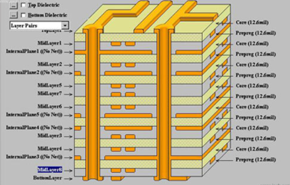
5. Stackup Design & RF Implementation
KKPCB designed a 4-layer hybrid stackup for 5G antenna modules to balance thermal and electrical performance:
-
L1: RF Feedline — Taconic RF-35 0.254 mm
-
L2: Ground — 1 oz Cu
-
L3: Control Layer — FR-4 0.18 mm
-
L4: Radiator — Taconic RF-35 0.508 mm
Design verification included HFSS simulation, ADS matching network tuning, and TDR validation at 39 GHz, achieving excellent impedance correlation between model and measurement (< ±0.05 dB variance).
6. Environmental & Reliability Validation
| Test Type | Condition | Result |
|---|---|---|
| Thermal Cycling | –40 ↔ 125 °C, 1000 cycles | No delamination, ΔDk < 0.01 |
| Humidity Test | 85 °C / 85 % RH, 1000 h | Df drift < 0.0001 |
| Mechanical Bending | 50 cycles at R5 mm | No crack or lift-off |
| Reflow Simulation | 260 °C peak 3 times | No warpage > 0.05 mm |
Results demonstrate that RF-35 PCBs maintain electrical and mechanical integrity under typical smartphone assembly and usage conditions.
7. Conclusion — Engineering Reliability Integration
The Taconic RF-35 PCB platform provides stable impedance, low loss, and excellent thermal uniformity for 5G smartphone antenna modules.
Through KKPCB’s precision lamination control, copper surface optimization, and real-time impedance verification, designers achieve phase-consistent RF performance even under thermal stress.
This integration ensures mass-production reliability for next-generation 5G devices.
8. Contact / CTA
For customized Taconic RF-35 PCB designs supporting 5G antenna, mmWave, and RF front-end modules, contact KKPCB Engineering Team.
We provide simulation-driven stackup design, impedance validation, and thermal stability analysis for smartphone and wireless communication systems.
