Engineering-Grade Substrate for Miniaturized High-Frequency Circuits
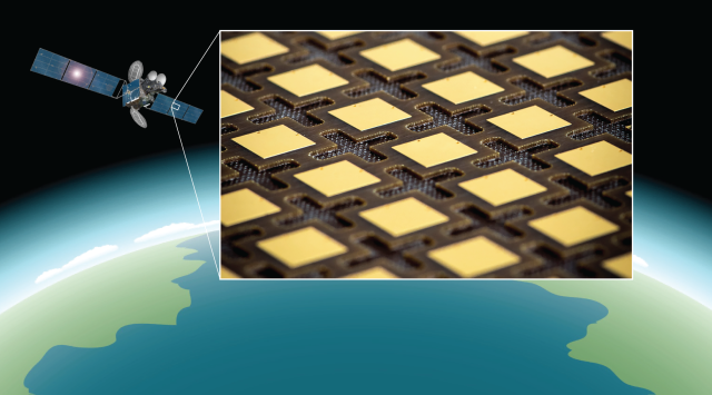
As mmWave systems advance toward higher frequencies (30–110 GHz), RF designers face dual challenges: size reduction and signal precision. Compact filters and power amplifiers demand tight impedance control, minimal phase shift, and consistent dielectric behavior even under thermal stress.
Rogers Duroid 6010, with a high dielectric constant (Dk = 10.2 ± 0.25) and low loss tangent (Df = 0.0023 @ 10 GHz), allows engineers to shrink circuit dimensions by nearly 40% compared to standard PTFE materials while maintaining low insertion loss and high phase stability.
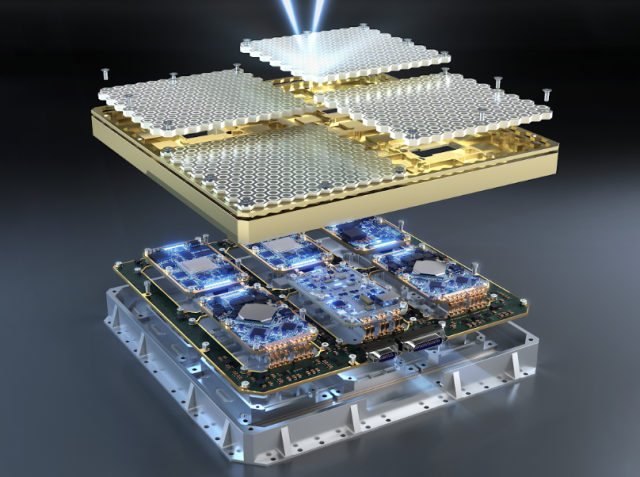
KKPCB’s high-frequency manufacturing platform leverages this material to deliver miniaturized, high-efficiency RF modules optimized for mmWave radar, aerospace, and defense communication systems.
Material Advantages — Precision and Compactness in One Platform
| Property | Value | Engineering Impact |
|---|---|---|
| Dielectric Constant (Dk) | 10.2 ± 0.25 | Enables reduced circuit footprint |
| Dissipation Factor (Df) | 0.0023 @ 10 GHz | Minimizes insertion loss |
| CTE (Z-Axis) | 24 ppm/°C | Enhances multilayer stack reliability |
| Thermal Conductivity | 0.66 W/m·K | Improves heat dissipation for power circuits |
Duroid 6010’s high Dk supports compact resonant structures—crucial in waveguide transitions, cavity filters, and high-gain amplifier stages—while its ceramic-filled PTFE base maintains dimensional and dielectric stability across temperature cycles.
KKPCB’s Precision Manufacturing Framework
To ensure high performance in every production lot, KKPCB applies tight process controls and RF validation protocols:
1. Dielectric Calibration and Pre-Baking
-
Moisture removal (120 °C / 4 h) for dimensional stability.
-
Dk verification across batches within ± 0.02.
2. Controlled Lamination Profile
-
Press cycle: 180 °C / 60 min / 200 psi.
-
Balanced cooling gradient reduces warpage to < 0.1 mm per 250 mm panel.
3. RF Electrical Validation
-
S-parameter verification up to 110 GHz.
-
Impedance deviation within ± 5 Ω.
-
Insertion loss variation < 0.05 dB/inch.
4. Thermal Stress Simulation
-
1000 cycles between –55 °C ↔ +150 °C with < 3 % impedance drift.
Case Study — Ka-Band Compact Bandpass Filter for Airborne Radar
Client: European radar system integrator
Objective: Miniaturize a 40 GHz bandpass filter while preserving low loss and high Q.
Design Specs:
-
Target bandwidth: 38–42 GHz
-
Insertion loss < 1.0 dB
-
Filter length reduction ≥ 35 % vs. RO4350B design
-
Substrate: Duroid 6010 (10 mil) + copper 0.5 oz rolled foil.
-
Integrated grounding vias for cavity resonance control.
-
Hybrid stackup using low-flow PTFE bonding film.
-
EM simulation + inline VNA verification (DC–50 GHz).
Results:
| Parameter | Target | Achieved |
|---|---|---|
| Insertion Loss | ≤ 1.0 dB | 0.82 dB |
| Return Loss | > 18 dB | 20.5 dB |
| Phase Shift Stability | < 1° | 0.7° |
| Size Reduction | 35 % | 36.8 % achieved |
Outcome:
The filter achieved a stable S-parameter response even after 1000 thermal cycles, confirming Duroid 6010’s suitability for high-frequency, compact radar modules.
Engineering Insights — Power Density and Structural Reliability
Duroid 6010’s high-Dk value enables compact filter and amplifier geometries, but also raises challenges in thermal expansion control and resonance suppression.
KKPCB engineers counter these effects through:
-
Hybrid stackup pairing with lower-Dk substrates (e.g., RO4350B) for CTE balancing.
-
Finite Element Simulation (FEM) to manage heat flow and mechanical stress.
-
Microvia fatigue analysis to ensure long-term reliability in high-power environments.
These design strategies enable stable impedance, low drift, and mechanical resilience, even in aerospace-grade modules exposed to extreme vibration and temperature cycles.
KKPCB Reliability Assurance
KKPCB enforces a five-layer quality assurance system to ensure production consistency:
-
Material Dk/Df verification per lot.
-
Lamination simulation for CTE balancing.
-
Inline VNA and TDR impedance checks up to 110 GHz.
-
Accelerated thermal/humidity cycling tests.
-
Cross-section inspection for delamination or voids.
This framework ensures each batch of Duroid 6010 PCBs meets the mechanical and electrical stability standards required for mission-critical mmWave systems.
Conclusion — Compact Power and Precision in One Substrate
Duroid 6010 PCBs deliver the ideal balance of miniaturization, low loss, and long-term thermal reliability.
Through KKPCB’s high-frequency process control and RF validation framework, engineers can confidently deploy this material in compact mmWave filters and RF power amplifiers where every dB and every degree matters.
-
Custom high-Dk stackup simulation.
-
Inline impedance verification for high-power boards.
-
Environmental reliability testing for aerospace and radar applications.
Contact KKPCB Engineering Support to evaluate your Duroid 6010 design or schedule a DFM review for compact mmWave filter and amplifier modules.
