Rigid-flex PCBs represent a groundbreaking advancement in electronics design, combining the best features of rigid boards and flexible circuits. By integrating high-density interconnect (HDI) technology, rigid-flex PCBs eliminate the need for traditional board-to-board connectors and simplify assembly processes. This article explores the design considerations, advantages, and applications of rigid-flex PCBs, along with strategies for optimizing their performance.
What Are Rigid-Flex PCBs?
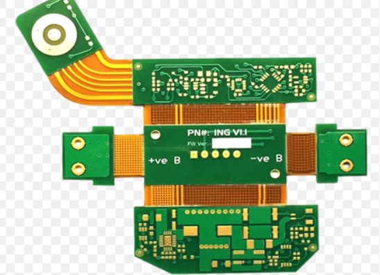
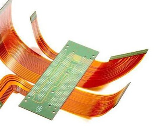
Rigid-flex PCBs are hybrid circuits that combine rigid and flexible substrates into a single structure. They are designed to replace traditional connectors and flex circuits, offering improved reliability, space savings, and design flexibility. Rigid-flex designs are particularly useful in applications where space is limited, and reliability is critical, such as wearable technology, medical devices, and aerospace systems.
Key Design Considerations for Rigid-Flex PCBs
Designing rigid-flex PCBs requires careful planning to address the unique challenges posed by their hybrid structure. Below are the key factors to consider:
1. Material Selection
- Flexible Materials: Polyimide is the most common material for flex sections due to its excellent thermal stability and flexibility.
- Rigid Materials: FR-4 is typically used for rigid sections, providing structural support and component mounting areas.
- Adhesives and Stiffeners: Adhesives bond the rigid and flex sections, while stiffeners provide mechanical support for connectors and components.
2. Layer Stacking
- Flex Layers: Flex sections often use fewer layers (e.g., 1–3 layers) to maintain flexibility.
- Rigid Layers: Rigid sections can have multiple layers (e.g., 8–12 layers) to accommodate complex routing and components.
- Impedance Control: Maintain consistent impedance by embedding signal layers between ground planes in both rigid and flex sections.
3. Bend Radius
- Ensure the flex sections have an adequate bend radius to prevent cracking or delamination. The bend radius depends on the material thickness and flexibility.
4. Component Placement
- Place components on rigid sections whenever possible to avoid mechanical stress on flex areas.
- Use zero insertion force (ZIF) connectors for easy assembly and reliable connections.
5. EMI Shielding
- Incorporate EMI shielding layers in the design to minimize electromagnetic interference, especially in high-frequency applications.
6. Thermal Management
- Account for thermal expansion and contraction in flex sections to prevent damage during operation.
Advantages of Rigid-Flex PCBs
Rigid-flex PCBs offer several benefits over traditional rigid or flex circuits:
- Space Savings: Eliminate the need for connectors, reducing the overall size and weight of the PCB.
- Improved Reliability: Fewer connectors mean fewer failure points, enhancing the durability of the circuit.
- Design Flexibility: Enable innovative form factors and configurations, such as wearable devices and foldable electronics.
- Simplified Assembly: Streamline the assembly process by integrating rigid and flex sections into a single unit.
- Enhanced Signal Integrity: Controlled impedance routing in both rigid and flex sections ensures consistent signal performance.
Applications of Rigid-Flex PCBs
Rigid-flex PCBs are used in a wide range of industries and applications, including:
1. Wearable Technology
- Smartwatches, fitness trackers, and medical wearables benefit from the compact and flexible design of rigid-flex PCBs.
2. Aerospace and Defense
- Rigid-flex PCBs are ideal for avionics, satellites, and military equipment, where reliability and space constraints are critical.
3. Medical Devices
- Medical imaging systems, pacemakers, and diagnostic equipment use rigid-flex PCBs for their durability and compact size.
4. Consumer Electronics
- Smartphones, tablets, and augmented reality (AR) devices leverage rigid-flex PCBs to achieve sleek designs and high performance.
5. Automotive
- Advanced driver-assistance systems (ADAS) and infotainment systems rely on rigid-flex PCBs for their robustness and space efficiency.
Routing Controlled Impedance Lines on Rigid-Flex PCBs
Maintaining controlled impedance is crucial for high-speed signal integrity. Here’s how to achieve it in rigid-flex designs:
- Embed Signal Layers: Place high-speed signal layers between ground planes in both rigid and flex sections to create a Faraday cage.
- Use Solid Ground Planes: Ensure continuous ground reference planes above and below signal layers to minimize impedance variations.
- Minimize Stubs: Avoid stubs in flex sections by routing signals through the center of the stack-up.
- Match Impedance: Use impedance calculators to match trace widths and spacing in both rigid and flex sections.
Challenges and Solutions in Rigid-Flex PCB Design
1. Complexity
- Challenge: Rigid-flex designs are more complex than traditional PCBs.
- Solution: Use advanced design tools and collaborate with experienced manufacturers.
2. Cost
- Challenge: Rigid-flex PCBs are more expensive due to specialized materials and processes.
- Solution: Optimize the design to minimize layer count and material usage.
3. Manufacturing Constraints
- Challenge: Rigid-flex PCBs require precise manufacturing processes.
- Solution: Follow design for manufacturability (DFM) guidelines and work closely with your manufacturer.
Rigid-flex PCBs are transforming the electronics industry by enabling innovative designs and improving reliability. By understanding the design considerations, advantages, and challenges, engineers can leverage rigid-flex technology to create cutting-edge products. Whether for wearable devices, aerospace systems, or consumer electronics, rigid-flex PCBs offer a versatile and reliable solution for modern electronics.
KKPCB conducts research on special processing technologies such as ordinary double-sided boards, thick copper circuit boards, high-frequency circuit boards, HDI circuit boards, rigid-flexible circuit boards, FPC flexible boards, buried blind hole circuit boards, and IC carrier boards. Provides PCB design, PCB layout, PCB prototyping and PCB assembly services.
