Professional HDI PCB Manufacturing | Prototype, Small Batch & Mass Production - KKPCB
 
// HDI PCB

High-Density Interconnect (HDI) PCB ManufacturingKKPCB

KKPCB specializes in advanced HDI (High Density Interconnect) PCB manufacturing, providing comprehensive support from DFM review and prototype development to volume production. Our expertise covers multi-level HDI structures, laser-drilled microvias, stacked and staggered vias, blind/buried vias, fine-line circuitry, and high-layer-count designs. Serving customers in telecommunications, automotive electronics, industrial control, medical devices, aerospace, and instrumentation industries, we are recognized for solving complex PCB challenges that demand superior signal integrity, miniaturization, and reliability. With advanced manufacturing processes and strict quality control, KKPCB delivers high-performance HDI PCBs that meet the requirements of next-generation electronic products.

// High-Reliability HDI PCBHigh-Reliability HDI PCB Manufacturing Services

KKPCB provides end-to-end PCB solutions, from design support and rapid prototyping to mass production of HDI, rigid-flex, aluminum, and RF circuit boards. Serving global clients across telecommunications, automotive, industrial, medical, aerospace, and instrumentation sectors, we specialize in solving complex PCB challenges with advanced technologies such as HDI structures (1+N+1, 2+N+2, 3+N+3), embedded/blind vias, and multilayer designs. Utilizing high-TG materials and low Dk/Df dielectrics, we ensure superior performance and reliability. Our manufacturing adheres to IPC-6012 Class 3 standards and holds ISO 9001, IATF 16949, UL, and other international certifications, guaranteeing compliance with industry requirements.

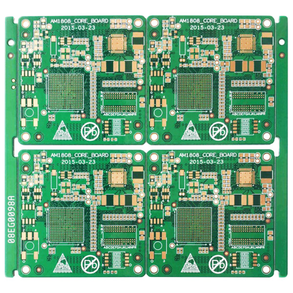
8-Layer 1+N+1 HDI PCB with ENIG Finish

8-Layer 1+N+1 HDI PCB with ENIG Finish

8-Layer 1+N+1 HDI PCB

8-Layer 1+N+1 HDI PCB

What is HDI PCB?

HDI (High-Density Interconnect) PCB is an advanced printed circuit board technology that enables high-density circuit distribution using micro blind and buried via technology. HDI boards feature both internal and external circuits, connected through precise hole drilling and metallization processes to achieve reliable interlayer connections.

Typically manufactured using build-up technology, the technical complexity increases with the number of lamination layers. Standard HDI boards usually use a single buildup, while advanced HDI boards adopt secondary or multiple lamination techniques, combined with cutting-edge methods such as via stacking, plated hole filling, and laser direct drilling.

With ongoing technological development, electronic design continuously improves device performance while reducing size, meeting the demand for miniaturization across applications — from mobile phones to smart defense systems. HDI PCBs are essential in enabling compact, high-performance, and reliable electronic devices in today’s fast-evolving technology landscape.

https://www.kkpcba.com/wp-content/uploads/2026/06/HDI-PCB.jpg

High density interconnects (HDI) PCB is an indispensable part of the electronics industry. Electronic components become smaller and lighter, but performance needs to be improved. To accommodate this situation, you need to pack more features into a smaller area. This is what HDI PCB provides.

Compared with traditional PCB, HDI PCB has a higher unit circuit density.  They use a combination of buried and blind holes, as well as microvia with a diameter of 0.006 inch or less.

The strict tolerances involved in using HDI printed circuit boards mean that you need to work with experienced suppliers. Even small defects or layout accidents can lead to serious problems. As a leading supplier of HDI printed circuit boards, KKPCB PCB provides a first-class circuit board, and its circuit density is much higher than that of traditional PCB.

Our HDI PCB manufacturing includes

At KKPCB, we provide advanced HDI PCB manufacturing solutions designed for high-speed, high-density, and high-reliability electronic applications, including AI computing systems, telecommunications, automotive electronics, industrial control, and RF/microwave systems.

Our HDI technologies support any-layer interconnection structures with stacked, staggered, and skip microvias, as well as copper-filled vias, via-in-pad plating, and advanced via fill processes to ensure excellent electrical performance and assembly reliability. We support complex HDI build-up designs from 1+N+1 up to 9+N+9, enabling ultra-high routing density for next-generation electronic systems.

Our manufacturing processes include sequential lamination, blind and buried vias, and Laser Direct Imaging (LDI) technology, ensuring high-precision alignment and stable multilayer registration. We are capable of producing ultra-fine circuitry down to 0.05 mm line/space and supporting fine-pitch BGA designs down to 0.3 mm.

To meet demanding signal integrity and RF performance requirements, KKPCB offers a comprehensive range of advanced materials, including low-loss laminates (I-Speed, FR408HR, Megtron 4, EM-888, N4000-13 series, TU-872 series), high-speed digital materials (Megtron 6, I-Tera MT40, Tachyon 100G, TU-883, IT-968 series), and RF/microwave laminates (Rogers RO4000/RO3000 series, RT/Duroid 5880, Taconic TLY series, Astra MT77). These material systems enable superior impedance control, low signal loss, and excellent thermal and electrical performance for high-frequency and high-speed applications.

https://www.kkpcba.com/wp-content/uploads/2026/06/ScreenShot_2026-06-10_013521_130.jpg

Overview HDI PCB Fabrication Capabilities

Description Standard Advanced
Line / Space 45 / 50 μm 35 / 40 μm
Laser Microvia / Pad 75 / 200 μm 50 / 150 μm
Mechanical Via / Pad 150 / 300 μm 125 / 250 μm
Thinnest Core Material 50 μm 50 μm
Thinnest Dielectric 60 μm 50 μm
Conductor Width Tolerance ±20% ±15%
Solder Mask Alignment ±25 μm ±15 μm
Layer Count Up to 58L Up to 68L

KKPCB has advanced advantages in HDI PCB manufacturing.  Advanced technology and equipment ensure that we can produce advanced HDI PCB.  Would you like to know how much your HDI PCB manufacturing cost is? Please submit a quotation request on this page at any time and describe your HDI PCB requirements in detail.  We will make a quotation for your HDI PCB soon.

HDI PCB Design Guide & Standard Stackup Library

Accelerate Your HDI PCB Development with Proven Engineering Resources

Designing High-Density Interconnect (HDI) PCBs requires far more than simply increasing routing density. Successful HDI designs must balance stackup architecture, signal integrity, power integrity, thermal performance, manufacturability, reliability, material selection, and overall project cost.

At KKPCB, we combine years of experience in advanced HDI PCB fabrication and assembly to provide engineers with practical design resources that help reduce development risks, shorten design cycles, improve first-pass manufacturing success rates, and accelerate product time-to-market.

Our engineering team has supported a wide range of complex HDI projects, including Any-Layer HDI, stacked microvias, staggered microvias, copper-filled vias, ultra-fine line structures, and high-speed digital platforms. The design guidelines and stackup resources provided here are based on real manufacturing capabilities and proven production experience.

Whether you are developing next-generation telecommunications equipment, automotive electronics, AI computing hardware, semiconductor test systems, industrial control equipment, medical devices, aerospace electronics, defense applications, or high-performance embedded systems, our HDI engineering resources can help you achieve a more reliable and manufacturable design.

HDI PCB Design Guide
Standard HDI Stackup Library
HDI Design Rules
HDI Material Selection Guide
DFM Checklist
IPC-2581 Stackup Files
Altium Designer Stackup Files
HDI Capability Matrix
HDI PCB Design Guide & Standard Stackup Library
Discover Our Family of Microvia Technologies

1 Standard & Sequential Microvia Structure

Supports 1-2 / 1-3 / 1-4 interconnections and advanced HDI architectures (1+N+1, 2+N+2, Any-Layer HDI).
Eliminates through vias, increases routing efficiency, reduces layer count, and enables compact PCB designs for complex systems.

2 Ultra-High Density Routing Capability

Supports fine geometries down to 0.25 mm pitch, enabling extremely dense routing for high-pin-count BGAs and advanced IC packages.
Optimized for next-generation applications such as AI computing, high-speed digital systems, and compact electronic modules.

3 Copper-Filled Via-in-Pad Technology

Provides a flat and planar surface for BGA assembly, eliminating solder voiding issues.
Enhances current carrying capability, mechanical strength, and thermal performance for high-power and high-reliability applications.

4 High-Performance RF & Signal Integrity Design

Engineered dielectric structures and microvia designs improve impedance control and reduce signal loss.
Ideal for high-speed, RF, 5G, radar, and communication systems requiring stable high-frequency performance.

5 Thermal & Reliability Optimization

Microvia structures enhance heat dissipation and current flow, improving long-term reliability under demanding operating conditions.
Suitable for automotive, industrial, aerospace, and mission-critical electronic systems.

Advanced HDI PCB Technologies

High-Density Solutions for Next-Generation Electronics

KKPCB supports a wide range of HDI technologies for advanced electronic applications.

HDI Structures

  • 1+N+1 HDI
  • 2+N+2 HDI
  • 3+N+3 HDI
  • Any-Layer HDI
  • ELIC (Every Layer Interconnect)

Microvia Technologies

  • Laser Drilled Microvias
  • Stacked Microvias
  • Staggered Microvias
  • Skip Microvias
  • Blind Vias
  • Buried Vias
  • Via-in-Pad Structures
  • Copper Filled Vias

Manufacturing Capabilities

  • Up to 68 PCB Layers
  • HDI Structures up to 9+N+9
  • Laser Via Diameter Down to 50μm
  • Fine Line / Space Down to 35/40μm
  • Up to 4 Sequential Lamination Cycles
  • Controlled Impedance Structures
  • High-Speed Digital PCB Manufacturing
  • RF & Microwave Hybrid Constructions
https://www.kkpcba.com/wp-content/uploads/2026/06/HDI-PCB-Manufacturing-DFM-Center.jpg
https://www.kkpcba.com/wp-content/uploads/2026/06/20-layer-6-stage-HDI-PCB.jpg
https://www.kkpcba.com/wp-content/uploads/2026/06/16-layer-5-stage-HDI-PCB-with-EPIG-finish.jpg

Frequently Asked Questions (FAQ)High-Density Interconnect (HDI) PCB FAQs

This FAQ section provides clear and practical answers to common questions about High-Density Interconnect (HDI) PCB design, manufacturing, materials, and performance. It is designed to help engineers, designers, and procurement teams better understand HDI technology, reduce design risks, and improve decision-making during product development. Whether you are working on stacked microvias, Any-Layer HDI structures, high-speed signal designs, or complex multilayer boards, these FAQs will help you quickly find reliable guidance based on real manufacturing experience and industry best practices.
What is HDI PCB?

HDI (High-Density Interconnect) PCB refers to a type of printed circuit board that has a higher wiring density per unit area compared to traditional PCB designs. HDI PCBs are characterized by finer lines and spaces, smaller vias and capture pads, and higher connection pad density. They are typically used in applications where space is limited and performance is critical.

Key Features of HDI PCBs:

  1. Microvias:HDI PCBs use microvias, which are smaller vias (typically less than 150 microns in diameter) that allow for more complex routing and higher density of connections.
  2. Laser Drilled Vias:The vias in HDI PCBs are usually drilled using laser technology, allowing for precision and smaller diameters compared to mechanical drilling.
  3. Stacked and Staggered Vias:HDI PCBs can feature stacked and staggered vias, enabling multiple layers to be interconnected more efficiently and compactly.
  4. Thin Dielectrics:HDI PCBs often use thin dielectric materials between layers, which contributes to their high-density interconnections and allows for closer spacing of traces.
  5. Buried and Blind Vias:These types of vias are commonly used in HDI PCBs to connect different layers without passing through the entire board, optimizing space and enhancing performance.
In which industries are HDI PCBs used?

HDI PCBs are applied in various industry sectors, including:

  1. Telecommunications:Used in smartphones, tablets, and networking equipment such as routers, switches, and 5G base stations due to their compact size and high performance.
  2. Automotive Electronics:Found in advanced driver assistance systems (ADAS), infotainment systems, and various control units, benefiting from the high-density and reliability of HDI PCBs.
  3. Medical Devices:Employed in diagnostic and monitoring equipment, such as MRI machines, CT scanners, and portable medical devices, where space and performance are critical.
  4. Aerospace and Defense:Utilized in avionics, communication systems, radar, and other military applications that require robust, high-performance, and reliable electronics.
  5. Consumer Electronics:Integral to products like wearable devices, gaming consoles, cameras, and other gadgets that demand small form factors and high functionality.
  6. Industrial Automation:Used in control systems, sensors, and machinery where precision and reliability are essential for industrial processes and automation.
  7. Computing and Data Centers:Essential for high-performance computing systems, servers, and storage solutions that require dense interconnections and efficient heat dissipation.
  8. IoT (Internet of Things):Found in various IoT devices, including smart home devices, wearable tech, and industrial IoT applications, where compact and efficient PCB designs are necessary.

HDI PCBs’ ability to offer high performance, compact size, and reliability makes them indispensable across these diverse and technologically advanced industry sectors.

What are the materials of HDI PCB boards?

HDI PCBs (High-Density Interconnect PCBs) are made from materials that support the high performance, miniaturization, and reliability required in advanced electronic applications. Here are some common materials used in HDI PCB fabrication:

1. FR-4 (Flame Retardant 4):

  • Description: A widely used fiberglass-reinforced epoxy laminate.
  • Characteristics: Good thermal and mechanical properties, cost-effective.
  • Applications: General-purpose HDI PCBs, consumer electronics.

2. High Tg FR-4:

  • Description: A variant of FR-4 with higher glass transition temperature (Tg).
  • Characteristics: Improved thermal stability and reliability.
  • Applications: High-performance HDI PCBs, automotive electronics.

3. Polyimide:

  • Description: A high-temperature resistant polymer.
  • Characteristics: Excellent thermal stability, flexibility, and chemical resistance.
  • Applications: Flexible HDI PCBs, aerospace, and military applications.

4. Rogers Materials:

  • Description: A series of high-frequency laminates, such as RO4000, RO3000, and RO4350.
  • Characteristics: Low dielectric constant (Dk), low loss, high frequency performance.
  • Applications: RF and microwave HDI PCBs, telecommunications, and medical devices.

5. BT Epoxy (Bismaleimide-Triazine):

  • Description: A type of epoxy with enhanced thermal and mechanical properties.
  • Characteristics: High thermal stability, good electrical properties.
  • Applications: HDI PCBs in high-performance computing and telecommunications.

6. Teflon (PTFE):

  • Description: Polytetrafluoroethylene, a high-frequency laminate.
  • Characteristics: Low dielectric constant, low dissipation factor, high frequency stability.
  • Applications: Microwave and high-frequency HDI PCBs, radar systems.

7. Ceramic-filled Laminates:

  • Description: Laminates filled with ceramic materials.
  • Characteristics: High thermal conductivity, low dielectric constant.
  • Applications: High-power and high-frequency HDI PCBs, RF applications.

8. Metal Core PCB (MCPCB):

  • Description: PCBs with a metal core (usually aluminum or copper) for better heat dissipation.
  • Characteristics: Excellent thermal management, mechanical strength.
  • Applications: LED lighting, power electronics, high-heat dissipation applications.

9. Aramid Fiber (Kevlar):

  • Description: A type of synthetic fiber known for its strength and heat resistance.
  • Characteristics: Lightweight, high tensile strength, good thermal properties.
  • Applications: Lightweight HDI PCBs, aerospace, and defense.

10. Glass-Reinforced Epoxy (Tg150/Tg170):

  • Description: Epoxy laminates with different glass transition temperatures (150°C and 170°C).
  • Characteristics: Varying levels of thermal stability and mechanical strength.
  • Applications: Different performance requirements in HDI PCBs, from consumer electronics to industrial applications.

Selecting the appropriate material for HDI PCBs depends on the specific requirements of the application, including thermal performance, electrical properties, mechanical strength, and cost considerations.

How to Choose a Professional HDI PCB Board Manufacturer?

To choose a professional HDI PCB manufacturer for producing your PCBs, consider the following factors:

  1. Experience and Expertise:Ensure the manufacturer has extensive experience and expertise in HDI PCB manufacturing, including familiarity with the latest technologies and design complexities.
  2. Technical Capabilities:Verify that the manufacturer possesses advanced manufacturing equipment and technologies, such as laser drilling, microvia technology, and precision plating processes.
  3. Quality Control and Certifications:Ensure the manufacturer has a robust quality control system and adheres to international standards like ISO 9001, IPC standards, and other relevant industry certifications.
  4. Material Selection and Supply Chain:Evaluate their expertise in selecting appropriate materials for HDI PCBs and their management of the supply chain to ensure material consistency and reliability.
  5. Production Capacity and Lead Time:Assess the manufacturer’s production capacity and lead times to ensure they can meet your project timelines and volume requirements.
  6. Design Support and Engineering Services:Look for manufacturers that offer design support and engineering services, including DFM (Design for Manufacturability) reviews, to optimize your PCB design for production.
  7. Testing and Inspection Capabilities:Check if the manufacturer has comprehensive testing and inspection capabilities, such as electrical testing, X-ray inspection, and other quality assurance processes.
  8. Customer Service and Communication:Evaluate their customer service and communication responsiveness to ensure smooth collaboration throughout the production process.

By carefully considering these factors, you can select a professional HDI PCB manufacturer that meets your requirements and ensures the production of high-quality PCBs.

What surface treatment processes are there for producing HDI PCBs?

When producing HDI (High-Density Interconnect) PCBs, several surface finish processes are commonly used to ensure optimal performance, reliability, and solderability. Here are the main surface finish processes for HDI PCBs:

  1. ENIG (Electroless Nickel Immersion Gold):
    • Process: Involves a layer of nickel followed by a layer of gold deposited on the copper surface.
    • Characteristics: Provides a flat, smooth surface suitable for high-frequency circuits, excellent solderability, and corrosion resistance.
  2. HASL (Hot Air Solder Leveling):
    • Process: The PCB is coated with molten solder and then leveled with hot air to remove excess solder.
    • Characteristics: Cost-effective and provides a reliable solder joint, but may not be as flat as other finishes, potentially impacting high-frequency performance.
  3. Immersion Tin:
    • Process: The copper surface is coated with a thin layer of tin through a chemical process.
    • Characteristics: Provides a flat surface suitable for fine-pitch components, good solderability, and is environmentally friendly.
  4. Immersion Silver:
    • Process: The copper surface is coated with a layer of silver through a chemical process.
    • Characteristics: Offers excellent electrical performance and corrosion resistance, suitable for high-frequency applications.
  5. OSP (Organic Solderability Preservatives):
    • Process: Applies a thin, organic layer to protect the copper surface from oxidation.
    • Characteristics: Simple and cost-effective, provides a flat surface, but may have a shorter shelf life compared to other finishes.
  6. ENEPIG (Electroless Nickel Electroless Palladium Immersion Gold):
    • Process: Involves layers of nickel, palladium, and gold deposited on the copper surface.
    • Characteristics: Offers excellent electrical performance, corrosion resistance, and is suitable for high-reliability applications.

Choosing the appropriate surface finish process for HDI PCBs is crucial for ensuring the performance and reliability of the final product. The selection depends on factors such as the specific application requirements, environmental conditions, and cost considerations.

How to Test HDI PCB Boards?

Testing HDI (High-Density Interconnect) PCB boards involves several steps to ensure their reliability and performance. Here are the key methods used to test HDI PCB boards:

  1. Automated Optical Inspection (AOI):
    • Visual Inspection: AOI uses cameras and image processing software to inspect the PCB for defects such as misaligned components, solder bridges, and insufficient solder joints. It is a non-contact method and can be used for pre- and post-reflow inspection.
  2. X-ray Inspection:
    • Internal Examination: X-ray inspection allows for the examination of internal structures, such as BGA (Ball Grid Array) solder joints, stacked vias, and filled vias. It helps identify hidden defects like voids, misalignments, and solder joint quality.
  3. Electrical Testing:
    • Flying Probe Test: This method uses probes to contact the PCB pads and vias to test for continuity and isolation. It is suitable for low to medium volume production and prototype testing.
    • In-Circuit Testing (ICT): ICT uses a bed-of-nails fixture to make contact with test points on the PCB. It tests for shorts, opens, resistance, capacitance, and other electrical characteristics. It is highly accurate but more suitable for high-volume production due to the cost of the fixtures.
  4. Functional Testing:
    • Performance Verification: Functional testing involves powering up the PCB and verifying its performance under real operating conditions. It checks the board’s functionality as a whole, ensuring that it meets the design specifications.
  5. Microsection Analysis:
    • Cross-Sectioning: This destructive test involves cutting a cross-section of the PCB to examine the internal structure under a microscope. It helps in analyzing the quality of vias, plating, and layer alignment.
  6. Environmental Stress Testing:
    • Thermal Cycling: The PCB is subjected to repeated heating and cooling cycles to test its reliability under thermal stress.
    • Humidity and Temperature Testing: The board is exposed to varying levels of humidity and temperature to ensure it can withstand environmental conditions it might encounter during its lifecycle.
  7. Solderability Testing:
    • Surface Finish Evaluation: This test evaluates the solderability of the PCB surface finishes to ensure reliable solder joints. It involves dipping the PCB into molten solder and assessing the quality of the solder joints.
  8. Impedance Testing:
    • Signal Integrity Check: For high-frequency HDI PCBs, impedance testing ensures that the transmission lines have the correct impedance values to maintain signal integrity.
  9. Burn-In Testing:
    • Long-Term Reliability: The PCB is powered and operated for an extended period to identify early failures and ensure long-term reliability. It is often used for critical applications where reliability is paramount.
  10. Electromagnetic Compatibility (EMC) Testing:
    • EMC Compliance: This testing ensures that the PCB does not emit excessive electromagnetic interference (EMI) and is immune to external EMI, which is crucial for meeting regulatory standards.

By employing these testing methods, manufacturers can ensure that HDI PCBs meet the required performance, reliability, and quality standards before they are deployed in end-user applications.

What are the advantages of HDI PCB?

HDI (High-Density Interconnect) PCBs offer several advantages over traditional PCBs, making them highly suitable for advanced and compact electronic applications. Here are the key advantages:

  1. Increased Density and Miniaturization:
    • Higher Component Density: HDI PCBs support higher component density due to finer lines and spaces, smaller vias, and closer pad spacing. This enables more compact and miniaturized designs.
    • Space Savings: The ability to incorporate more components and interconnections within a smaller area allows for the creation of smaller and lighter electronic devices.
  2. Improved Electrical Performance:
    • Shorter Signal Paths: The use of microvias and advanced stack-up configurations reduces signal path lengths, leading to improved signal integrity and reduced signal loss.
    • Lower Signal Delays: Shorter interconnections result in lower signal delays, which is crucial for high-speed and high-frequency applications.
  3. Enhanced Design Flexibility:
    • Complex Interconnects: HDI technology allows for complex interconnects with multiple layers and various via structures (e.g., blind, buried, and stacked vias), enabling more intricate and efficient designs.
    • Advanced Layer Stack-Up: The ability to use sequential lamination and build-up processes provides designers with greater flexibility in creating multi-layered, high-performance PCBs.
  4. Better Thermal Management:
    • Efficient Heat Dissipation: HDI PCBs often use advanced materials with better thermal properties, improving heat dissipation and overall thermal management.
    • Thermal Vias: The use of microvias and other advanced via technologies can enhance thermal conductivity and help manage heat more effectively.
  5. Higher Reliability and Durability:
    • Enhanced Mechanical Strength: The smaller and more tightly packed interconnections in HDI PCBs can lead to improved mechanical strength and durability.
    • Reduced Risk of Defects: Advanced manufacturing processes and materials used in HDI PCBs can reduce the risk of defects, such as delamination and thermal stress failures.
  6. Improved Signal Integrity:
    • Lower Electromagnetic Interference (EMI): Shorter signal paths and better material choices can reduce EMI and crosstalk, leading to improved signal integrity and performance.
    • Controlled Impedance: HDI PCBs allow for better control over impedance, which is critical for high-speed and high-frequency signal transmission.
  7. Cost-Effectiveness for High-Volume Production:
    • Reduced Layer Count: Despite the higher initial manufacturing costs, the ability to achieve higher density and functionality with fewer layers can lead to cost savings in high-volume production.
    • Integration of Advanced Features: The capability to integrate advanced features, such as embedded components and complex interconnects, can reduce the need for additional components and assemblies, further lowering overall costs.
  8. Suitability for Advanced Applications:
    • Mobile and Wearable Devices: HDI PCBs are ideal for mobile phones, tablets, and wearable devices where space is limited, and high performance is required.
    • High-Speed Communication: HDI PCBs are well-suited for high-speed communication devices, including networking equipment and RF applications.
    • Automotive and Aerospace: The reliability and performance of HDI PCBs make them suitable for demanding automotive and aerospace applications.

These advantages make HDI PCBs a preferred choice for many modern electronic applications, where performance, miniaturization, and reliability are critical factors.

What are the special processes of HDI PCB?

HDI (High-Density Interconnect) PCBs involve several special processes that differentiate them from traditional PCBs. Here are some of the key processes involved in HDI PCB manufacturing:

  1. Laser Drilling:
    • Microvias: HDI PCBs use microvias, which are small vias with diameters typically less than 150 microns. Laser drilling is used to create these microvias, enabling higher component density and better electrical performance.
  2. Sequential Lamination:
    • Build-up Layers: HDI PCBs often have multiple layers added sequentially. This involves laminating additional layers of dielectric material and copper to the core PCB and drilling and plating vias in multiple steps.
  3. Via Filling:
    • Filled and Capped Vias: Microvias and other vias in HDI PCBs are often filled with conductive or non-conductive materials and then plated over to provide a smooth surface for further processing.
  4. Stacked and Staggered Vias:
    • Stacked Vias: In some designs, vias are stacked on top of each other across multiple layers, requiring precise alignment and filling techniques.
    • Staggered Vias: Vias can also be staggered, where they are offset from layer to layer to avoid alignment issues and improve reliability.
  5. Advanced Materials:
    • High-Performance Substrates: HDI PCBs often use advanced materials with lower dielectric constants and lower loss tangents to support high-frequency signals and improve signal integrity.
  6. Copper Thickness Control:
    • Thin Copper Layers: Precise control over copper thickness is crucial in HDI PCBs to ensure fine line and space requirements are met.
  7. Surface Treatments:
    • Surface Finishes: HDI PCBs may use various surface finishes such as ENIG (Electroless Nickel Immersion Gold), OSP (Organic Solderability Preservative), or immersion silver to ensure good solderability and reliability.
  8. Solder Mask and Silkscreen:
    • Precision Application: Applying solder mask and silkscreen with high precision is important to avoid covering fine features and to ensure accurate component placement.
  9. Testing and Inspection:
    • Advanced Testing Methods: HDI PCBs undergo rigorous testing and inspection processes, including automated optical inspection (AOI), X-ray inspection, and electrical testing to ensure all connections and features are intact and functioning.

These processes collectively allow HDI PCBs to support higher component density, finer lines and spaces, and improved electrical performance, making them suitable for advanced electronic applications like smartphones, tablets, and other high-performance computing devices.

How are HDI PCBs different from ordinary PCBs?

HDI (High-Density Interconnect) PCBs differ from ordinary PCBs in several significant ways. These differences enable HDI PCBs to support advanced electronic applications requiring higher performance, greater component density, and better signal integrity. Here are the key differences:

  1. Layer Structure:
    • HDI PCBs: Often have multiple layers with advanced stack-up configurations, including microvias, buried vias, and blind vias. They may use sequential lamination processes to add additional layers.
    • Ordinary PCBs: Typically have simpler layer structures with through-hole vias that go through the entire board.
  2. Via Technology:
    • HDI PCBs: Use microvias (very small vias with diameters less than 150 microns), blind vias (connecting outer layers to inner layers without going through the entire board), and buried vias (connecting inner layers without reaching outer layers).
    • Ordinary PCBs: Mostly use through-hole vias that extend from the top to the bottom layer of the board.
  3. Density and Miniaturization:
    • HDI PCBs: Support higher component density due to finer lines and spaces, smaller vias, and closer pad spacing. This allows for more compact and miniaturized designs.
    • Ordinary PCBs: Have lower component density and are generally used for less complex designs.
  4. Material Selection:
    • HDI PCBs: Often use high-performance materials with lower dielectric constants and lower loss tangents to support high-frequency applications and improve signal integrity.
    • Ordinary PCBs: Typically use standard FR4 materials, which may not be suitable for high-frequency or high-speed applications.
  5. Signal Integrity and Performance:
    • HDI PCBs: Offer improved signal integrity and performance due to the shorter and more direct signal paths provided by microvias and advanced materials.
    • Ordinary PCBs: May suffer from signal degradation over longer paths and through thicker boards.
  6. Manufacturing Complexity:
    • HDI PCBs: Require more advanced manufacturing processes, such as laser drilling for microvias, sequential lamination, and precise copper thickness control. These processes add complexity and cost to the manufacturing.
    • Ordinary PCBs: Use more straightforward manufacturing processes, making them less expensive and easier to produce.
  7. Applications:
    • HDI PCBs: Used in advanced applications such as smartphones, tablets, wearable devices, high-frequency RF circuits, and other compact, high-performance electronic products.
    • Ordinary PCBs: Used in a wide range of general applications, including consumer electronics, industrial equipment, and automotive electronics, where extreme miniaturization and high performance are not as critical.
  8. Thermal Management:
    • HDI PCBs: Often have better thermal management due to the use of advanced materials and the ability to design more efficient thermal paths.
    • Ordinary PCBs: May require additional thermal management solutions, such as heat sinks or thermal vias, to handle heat dissipation.

These differences enable HDI PCBs to meet the demands of modern electronic devices that require high performance, miniaturization, and reliability, whereas ordinary PCBs are suited for less demanding applications.

What are the difficulties in HDI PCB design and manufacturing?

Designing and manufacturing HDI (High-Density Interconnect) PCBs present several challenges due to the advanced technologies and processes involved. Here are the primary difficulties:

Design Challenges

  1. Complex Layouts:
    • High Component Density: Achieving high component density requires precise placement and routing, which can be challenging.
    • Fine Line/Space: Designing with very fine lines and spaces increases the risk of shorts and opens.
  2. Thermal Management:
    • Heat Dissipation: Managing heat in densely packed PCBs can be difficult, requiring careful thermal analysis and design.
  3. Signal Integrity:
    • High-Frequency Signals: Maintaining signal integrity at high frequencies necessitates meticulous impedance control and minimizing signal loss.
    • Electromagnetic Interference (EMI): Preventing EMI and crosstalk in high-density designs requires careful layer stacking and shielding.
  4. Stack-Up Configuration:
    • Complex Layer Stacking: Determining the optimal layer stack-up to balance performance, cost, and manufacturability is complex.
    • Sequential Lamination: Incorporating multiple lamination cycles can complicate the design process.
  5. Via Design:
    • Microvias: Designing reliable microvias and managing their placement and size can be challenging.
    • Via-in-Pad: This technique can improve routing but complicates manufacturing due to potential solderability issues.
  6. Material Selection:
    • Advanced Materials: Choosing materials with suitable dielectric properties and thermal stability is crucial but can limit design flexibility.

Manufacturing Challenges

  1. Advanced Drilling Techniques:
    • Laser Drilling: Creating precise microvias with lasers is more challenging and costly compared to mechanical drilling.
    • Via Filling: Filling and plating microvias and via-in-pad structures require advanced processes and quality control.
  2. Sequential Lamination and Registration:
    • Multiple Lamination Cycles: Each additional lamination cycle increases the complexity and risk of misalignment.
    • Layer-to-Layer Registration: Ensuring precise alignment between layers is critical and more difficult with complex stack-ups.
  3. Precise Etching and Imaging:
    • Fine Lines and Spaces: Achieving the required resolution for fine lines and spaces demands advanced photolithography and etching techniques.
    • Uniform Copper Thickness: Maintaining uniform copper thickness is crucial for impedance control and reliability.
  4. Material Handling:
    • Specialized Materials: Handling and processing advanced materials with specific dielectric and thermal properties require specialized equipment and processes.
    • Dimensional Stability: Ensuring materials remain stable through multiple thermal cycles and processing steps is challenging.
  5. Solderability and Assembly:
    • Surface Finishes: Achieving consistent and reliable surface finishes (e.g., ENIG, OSP) for fine-pitch components is more difficult.
    • Component Placement: Placing and soldering small components on high-density boards require precise machinery and techniques.
  6. Quality Control and Testing:
    • Inspection: Inspecting high-density designs for defects (e.g., AOI, X-ray) is more complex and time-consuming.
    • Electrical Testing: Ensuring thorough electrical testing for continuity, isolation, and performance is crucial but more difficult with dense and complex designs.

// Expert Support for Your HDI PCB DesignsGet Professional HDI Engineering Guidance

// KKPCB Blog

Read Our Latest News

Explore the latest in PCB manufacturing innovations, practical design strategies, and expert insights into assembly processes—along with key updates from the global electronics industry. The KKPCB Blog is your trusted resource for knowledge, expertise, and innovative solutions in the world of printed circuit boards.
Phase Stability and Low-Loss RF Implementation of Automotive Electronics PCBs in Automotive Radar and Sensor Fusion Platforms
Engineering Context Modern automotive electronics platforms are rapidly evolving toward higher levels of autonomy, requiring seamless integration of radar sensors, cameras, LiDAR modules, GNSS receivers, and centralized computing architectures. At the heart of these systems lies the Automotive Electronics PCB, which serves as the critical interconnection platform for high-frequency RF signals, high-speed digital interfaces, and...
EPIG vs ENIG vs ENEPIG for RF, microwave, high-speed and fine-pitch PCB designs
For standard SMT PCBs, surface finish is often selected for solderability, storage life and cost. But for RF, microwave, high-speed PCB, HDI, fine-pitch, radar, satellite communication, 5G RF and defense communication PCBs, surface finish can become part of the electrical performance discussion. The key question is not simply: Which gold finish is better? The better...
Double Layer HF PCB: High-Frequency Two-Layer PCB Solutions for RF and Microwave Applications
Why Double Layer HF PCB Technology Is Important Modern wireless communication systems continue evolving toward: Higher operating frequencies Faster wireless transmission Compact RF module integration Low-loss microwave communication Miniaturized antenna systems Applications such as: RF communication modules IoT wireless devices Automotive radar sensors 5G communication systems Microwave antenna platforms require PCB solutions capable of delivering:...