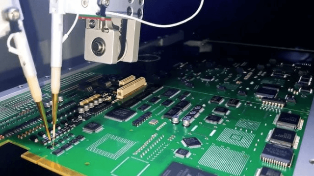
In modern electronics manufacturing, accuracy is everything. Before a chip or circuit board reaches the market, it must go through rigorous testing to verify functionality, reliability, and performance. This process is typically carried out using Automated Test Equipment (ATE).
At the center of this system lies the ATE Test PCB, a specialized printed circuit board designed to interface between the testing equipment and the device under test (DUT).
Unlike standard circuit boards, ATE Test PCBs must handle high signal integrity, repeated mechanical stress, and precise electrical measurements. Their design directly affects testing accuracy and production efficiency.
What Is an ATE Test PCB?
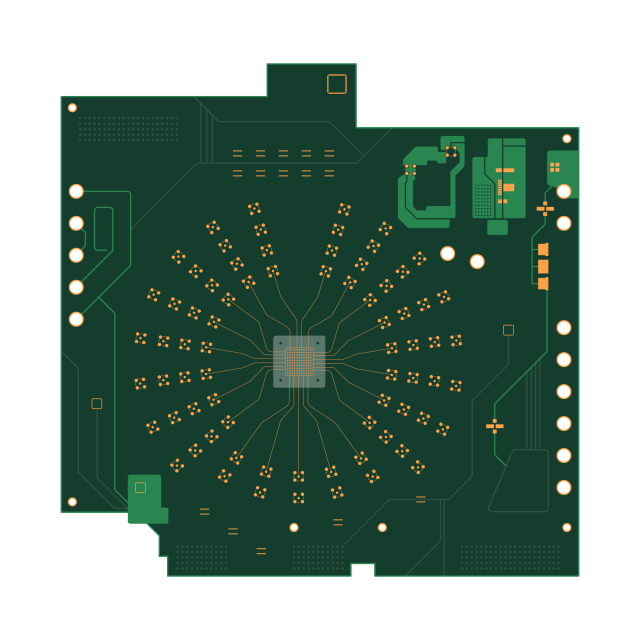
An ATE Test PCB is a customized circuit board used in automated test systems to connect testing instruments with semiconductor devices or electronic modules.
It performs several critical functions:
• Routes high-speed signals between the tester and DUT
• Provides mechanical support for sockets and connectors
• Maintains signal integrity during high-frequency measurements
• Ensures reliable contact for repeated test cycles
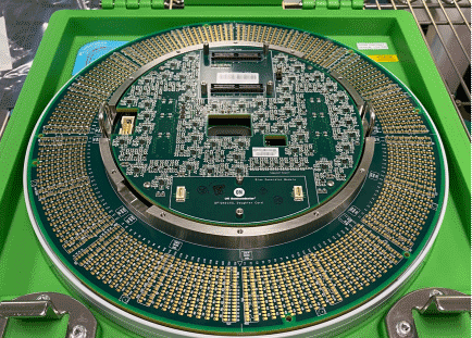
Because ATE systems often test thousands of units daily, these PCBs must be extremely durable and electrically stable.
Key Design Considerations for ATE Test PCB
Designing a PCB for automated test systems requires more engineering attention than ordinary circuit boards.
Signal Integrity
High-speed digital and RF signals demand controlled impedance routing. Poor design can introduce noise, reflection, and measurement errors.
High-Density Routing
ATE boards often include hundreds or thousands of test channels. This requires multilayer PCB structures and advanced routing strategies.
Mechanical Durability
Test sockets are repeatedly inserted and removed. Reinforced PCB structures and robust materials prevent warping and cracking.
Thermal Stability
ATE systems can generate significant heat during long testing cycles. Thermal management and material selection become essential.
Materials Used in ATE Test PCBs
Material selection strongly influences performance.
Common PCB materials include:
High-frequency laminates
Used for RF and microwave testing environments where signal loss must be minimized.
High-Tg FR-4 materials
Provide stability for high-temperature testing conditions.
Low-loss dielectric materials
Essential for high-speed semiconductor testing applications.
The choice of material depends heavily on the target device, testing frequency, and required reliability.
Applications of ATE Test PCBs
ATE Test PCBs are widely used across several high-technology industries.
Semiconductor Manufacturing
Chipmakers rely on ATE systems to validate integrated circuits before packaging and shipment.
Consumer Electronics
Smartphones, laptops, and IoT devices all require automated testing during production.
Automotive Electronics
Advanced driver assistance systems (ADAS), sensors, and control units require strict testing for safety compliance.
Telecommunications Equipment
High-frequency RF modules used in 5G and wireless communication must undergo precise automated testing.
Why High-Quality ATE Test PCBs Matter
Testing accuracy directly affects product reliability. A poorly designed ATE board can lead to false failures, inaccurate measurements, and reduced production yield.
High-quality PCB manufacturing ensures:
• stable signal transmission
• long service life under repeated testing cycles
• compatibility with high-speed testing environments
For electronics manufacturers, investing in reliable ATE Test PCB solutions ultimately reduces testing costs and improves product quality.
