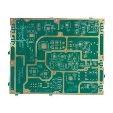
Introduction to RF-35 PCB
An RF-35 PCB is a high-frequency printed circuit board manufactured using RF-35 laminate from Taconic.
RF-35 is a glass-reinforced, PTFE-based composite material engineered to provide low dielectric loss, excellent phase stability, and consistent electrical performance across a wide frequency range.
It is widely applied in RF and microwave systems where signal accuracy and repeatability are critical.
Electrical Performance Characteristics
RF-35 laminate provides:
-
Dielectric constant (Dk): approximately 3.5
-
Low dissipation factor (Df)
-
Stable electrical properties across temperature variations
-
Minimal signal attenuation at microwave frequencies
These properties make RF-35 PCB suitable for applications operating from GHz to microwave frequency bands.
Key Advantages of RF-35 PCB
1. Excellent Phase Stability
For RF systems such as antenna arrays and phased modules, maintaining phase consistency is essential. RF-35 offers:
-
Tight dielectric tolerance
-
Minimal drift across temperature cycles
-
Predictable signal propagation speed
This ensures stable performance in communication and radar systems.
2. Low Insertion Loss
Low dielectric loss reduces signal degradation over long trace distances. This is particularly important for:
-
RF power amplifiers
-
Antenna feed networks
-
Microwave transmission paths
Lower insertion loss improves overall system efficiency.
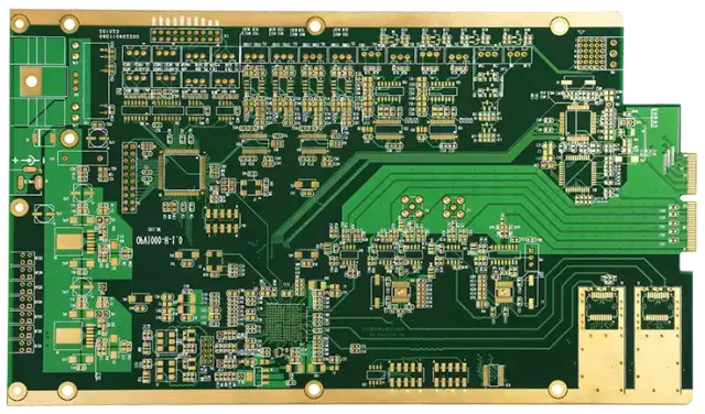
3. Hybrid Multilayer Compatibility
RF-35 PCB can be integrated into hybrid stack-ups, combining:
-
RF-35 layers for high-frequency signals
-
FR4 layers for digital and control circuits
This approach helps balance performance and cost, especially in telecom and infrastructure equipment.
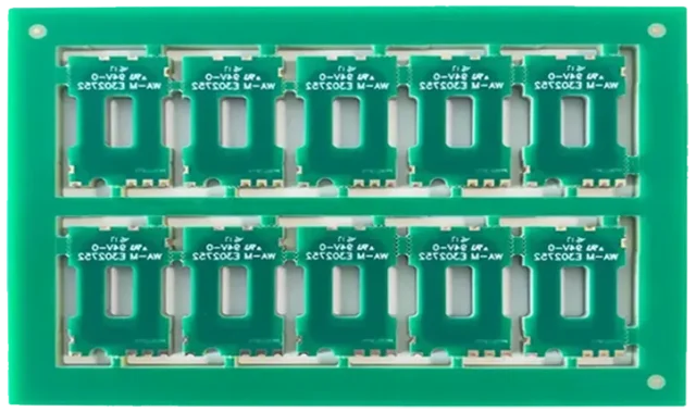
4. Mechanical Strength and Process Stability
Unlike pure PTFE materials, RF-35’s glass reinforcement provides:
-
Improved dimensional stability
-
Better drilling accuracy
-
Reliable multilayer lamination
This supports consistent mass production and tight impedance control.
Design Considerations
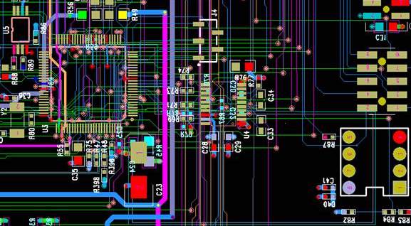
When designing an RF-35 PCB, engineers focus on:
-
Controlled impedance routing
-
Proper ground plane configuration
-
Minimizing stub lengths and via transitions
-
Careful stack-up planning
Attention to these factors ensures optimal RF performance and signal integrity.
Typical Applications
RF-35 PCB is commonly used in:
-
Wireless communication modules
-
Microwave backhaul systems
-
Antenna array boards
-
RF front-end circuits
-
Radar subsystems
-
Industrial RF transmitters
Its combination of low loss and structural stability makes it suitable for both commercial and infrastructure-level equipment.
RF-35 PCB vs Standard FR4 PCB
| Feature | FR4 PCB | RF-35 PCB |
|---|---|---|
| Dielectric Stability | Moderate | High |
| Dissipation Factor | 0.02–0.03 | Very Low |
| Microwave Performance | Limited | Excellent |
| Phase Stability | Basic | Precise |
| Multilayer Capability | Good | Excellent |
RF-35 PCB provides superior RF performance compared to conventional FR4 materials.
Conclusion
RF-35 PCB offers a balanced combination of low-loss electrical performance, phase stability, and manufacturing reliability.
For RF and microwave applications where signal precision, repeatability, and long-term stability are required, RF-35 laminate is a dependable material choice.
Engineers designing communication infrastructure, antenna systems, and RF modules can rely on RF-35 PCB to deliver stable and efficient high-frequency performance.
