Why PCB Thermal Conductivity Matters
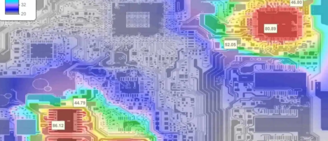
As power density and operating frequencies continue to increase, thermal management has become a critical factor in PCB design. Excessive heat can lead to signal degradation, reduced component lifespan, and even system failure.
This article from KKPCB provides a technical comparison of PCB thermal conductivity across four commonly used substrate materials:
-
FR4 PCBs
-
Ceramic PCBs
-
Metal Core PCBs (MCPCB)
-
Rogers High-Frequency Laminates
By understanding their thermal performance, material composition, and application scenarios, engineers can select the most suitable PCB substrate for their designs.
Thermal Conductivity Fundamentals in PCBs
Thermal conductivity (K) describes a material’s ability to transfer heat and is defined as:K = Q × L / (A × ΔT)
Where:
-
K = Thermal conductivity (W/m·K)
-
Q = Heat flow (W)
-
L = Material thickness (m)
-
A = Cross-sectional area (m²)
-
ΔT = Temperature difference (K)
In PCB systems, thermal conductivity directly affects:
-
Heat spreading from power components
-
Temperature rise of IC junctions
-
Long-term reliability and stability
FR4 PCB Thermal Conductivity and Limitations
FR4 Material Composition
FR4 is a glass fiber–reinforced epoxy resin laminate, widely used due to its low cost and mature manufacturing process.
-
Glass fiber content: 30%–70% (by weight)
-
Provides mechanical strength and insulation
Thermal Conductivity of FR4
FR4 exhibits anisotropic thermal behavior:
-
In-plane (X–Y): 0.25 – 0.30 W/m·K
-
Through-thickness (Z): 0.10 – 0.20 W/m·K
Heat transfer through the board thickness is extremely limited.
Design Challenges
-
Poor heat dissipation for localized hot spots
-
Thermal vias offer limited improvement
-
Not suitable for high-power or high-heat-flux designs
Typical FR4 Applications
-
Consumer electronics
-
Computers & peripherals
-
Automotive electronics (non-power modules)
-
Cost-sensitive designs
FR4 remains the most economical PCB material, but not ideal for thermal-critical applications.
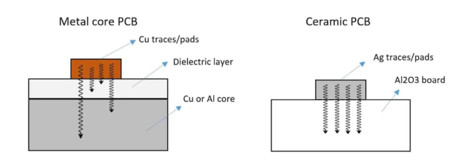
Ceramic PCB Thermal Performance
Ceramic PCB Materials
Ceramic PCBs are made from high-purity ceramic substrates, commonly:
-
Alumina (Al₂O₃): 92%–99% purity
-
Aluminum Nitride (AlN): >90% purity
Metal layers (Cu or Al) are bonded to enable circuit routing.
Thermal Conductivity
Ceramic materials offer an order of magnitude higher thermal conductivity than FR4:
-
Alumina: 24 – 30 W/m·K
-
Aluminum Nitride: 170 – 250 W/m·K
Performance Advantages
-
Excellent heat spreading and dissipation
-
Low thermal resistance
-
High dimensional stability (no warping)
Typical Ceramic PCB Applications
-
Power electronics
-
EV inverters and chargers
-
RF & microwave circuits
-
Aerospace and defense systems
Ceramic PCBs are expensive and require specialized fabrication.
Metal Core PCB (MCPCB) Heat Dissipation
Metal Core PCB Structure
MCPCBs include a thick metal base layer:
-
Aluminum or copper core: 0.8 mm to several mm
-
Dielectric layer bonds copper circuitry to metal core
Thermal Conductivity
-
Aluminum: 150 – 230 W/m·K
-
Copper: ~400 W/m·K
Thermal Advantages
-
Metal base acts as an integrated heat sink
-
Excellent heat spreading and thermal mass
-
Heat dissipation through backside possible
Typical MCPCB Applications
-
High-power LED lighting
-
Power converters & inverters
-
Motor drives
-
Renewable energy electronics
If maximum heat dissipation is required, MCPCB is often the best solution.
Rogers PCB Thermal Properties and RF Performance
Rogers PCB Materials Overview
Rogers laminates use fluoropolymer resin systems, often combined with ceramic fillers for enhanced performance.
Common Rogers materials:
-
RO4350B / RO4350 LoPro
-
RO4003C
-
RT/duroid 6202
-
RT/duroid 6035HTC
Thermal Conductivity of Rogers Materials
-
RO4003C: 0.69 W/m·K
-
RO4350 LoPro: 1.5 W/m·K
-
RT/duroid 6202PR: 1.57 W/m·K
-
RT/duroid 6035HTC: 1.7 W/m·K
Significantly higher than FR4, while maintaining excellent RF properties.
Design Advantages
-
Balanced thermal and dielectric performance
-
Low CTE mismatch with copper
-
Excellent signal integrity at high frequencies
Typical Rogers PCB Applications
-
RF & microwave PCBs
-
High-speed digital circuits
-
Power amplifiers
-
Automotive radar
-
Semiconductor test boards
PCB Thermal Conductivity Comparison Table
| PCB Material | Core Composition | Thermal Conductivity (W/m·K) |
|---|---|---|
| FR4 | Epoxy + Glass Fiber | ~0.25 |
| Ceramic PCB | Al₂O₃ / AlN | 25 – 250 |
| Metal Core PCB | Aluminum / Copper | 150 – 400 |
| Rogers Laminate | Fluoropolymer | 0.7 – 1.7 |
How to Choose the Right PCB Substrate for Thermal Management
-
FR4 → Low cost, low heat
-
Ceramic PCB → Extreme thermal + RF performance
-
Metal Core PCB → Maximum heat dissipation
-
Rogers PCB → Balanced thermal + high-frequency performance
Thermal modeling and system-level analysis are essential when selecting materials.
PCB Thermal Conductivity – FAQs
Q1: How does thermal conductivity affect component temperature?
Higher thermal conductivity lowers thermal resistance, reducing junction temperature at the same power level.
Q2: Why are ceramic PCBs more expensive than FR4?
Higher raw material cost, tighter process control, lower yields, and specialized equipment.
Q3: When should ceramic or MCPCB be used instead of FR4?
For RF, power electronics, high-brightness LEDs, or applications exceeding FR4’s heat capacity.
Q4: Can FR4 thermal performance be improved?
Thermal vias and thicker copper help slightly, but external heat sinks are still required.
Q5: Is dielectric constant related to thermal conductivity?
Indirectly. Low-Dk materials often show better thermal behavior, but filler content is also critical.
KKPCB Thermal PCB Solutions
At KKPCB, we provide:
-
FR4, Rogers, Ceramic, and Metal Core PCBs
-
High thermal conductivity PCB manufacturing
-
RF & power PCB engineering support
-
Prototype to mass production
Contact KKPCB today to optimize your PCB thermal design.
