// Advanced Flexible PCB Manufacturing SolutionsYour Reliable Partner for Flexible PCB Solutions
Flexible PCBs, also known as FPCs (Flexible Printed Circuits), are advanced electronic substrates designed to offer exceptional flexibility, high wiring density, and a thin, lightweight form factor. Their compact design reduces routing constraints and optimizes space, making them ideal for modern electronic devices where size, weight, and reliability are critical. FPCs enable complex three-dimensional configurations and bending without compromising electrical performance, perfectly supporting the trend toward miniaturized, portable, and high-performance electronics. From consumer gadgets and wearable devices to automotive and industrial applications, flexible PCBs provide a reliable, efficient, and space-saving solution that meets the demands of cutting-edge electronic designs.
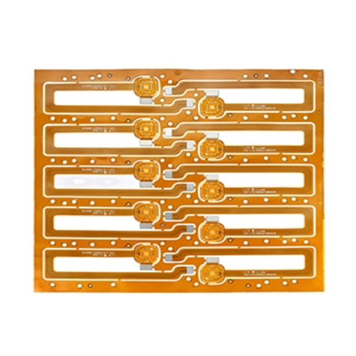
Fingerprint Identification FPCB
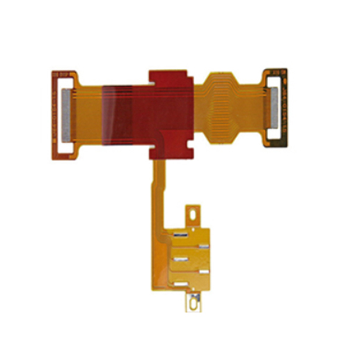
Player 4-layer flexible circuit board
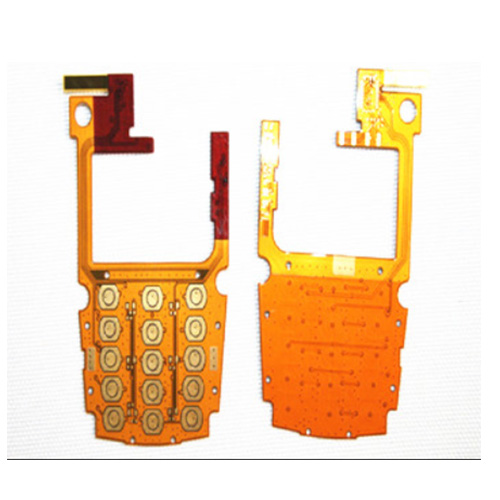
Multilayer mobile phone FPC circuit board
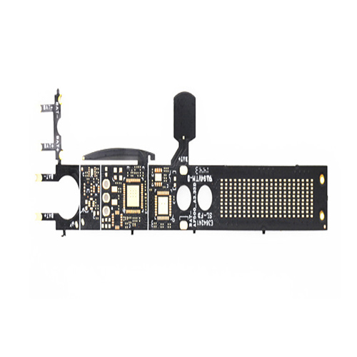
Smart Products FPC Circuit Board
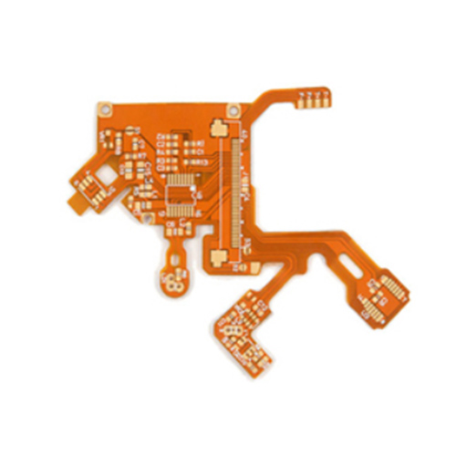
PI PTFE PCB multi-layer flexible board
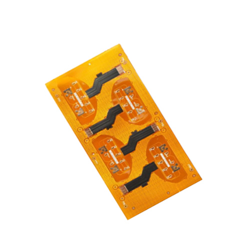
4-layer flexible impedance PCB
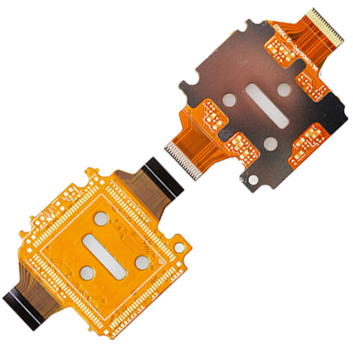
Multilayer FPC module board
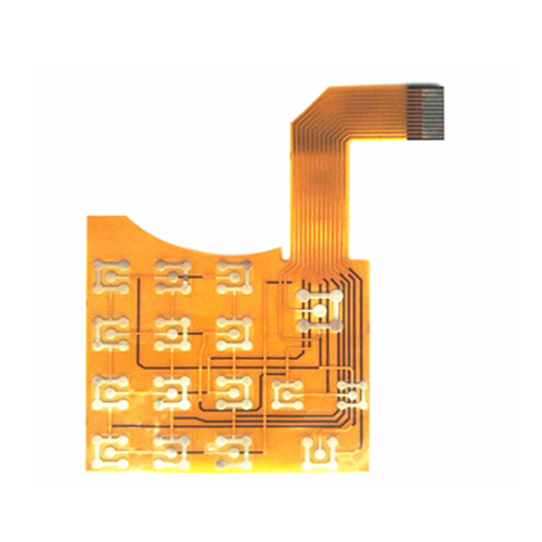
Double-sided FPC circuit board
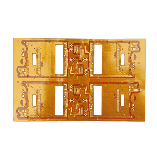
LCD display fpc flexible circuit board
What is Flex PCB?
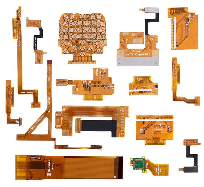
Flexible printed circuit board, also known as a flexible circuit board, flex PCB, or FPC for short, has the advantages of high wiring density, lightweight, thin thickness, less wiring space limitation, and high flexibility. It fully conforms to the development trend of light and short electronic products and is an effective solution to meet the requirements of miniaturization and mobility of electronic products.
Flex PCB fabrication capability
| Project | Prototype | Mass Production |
|---|---|---|
| Product Type | Single FPC, Double-Sided FPC Board, Layered Board, Hollowed-Out FPC Board, Multi-Layer FPC, Rigid-Flex Board | Single FPC, Double-Sided FPC Board, Layered Board, Hollowed-Out FPC Board, Multi-Layer FPC, Rigid-Flex Board |
| Number of Layers | 1–8 Layer Flexible PCB | 1–6 Layer Flexible PCB |
| Maximum Finished Size | 250×4000 mm | 250×4000 mm |
| Board Thickness | 0.06 mm – 1.0 mm | 0.08 mm – 0.8 mm |
| Min. Line/Space | 0.045 mm / 0.045 mm | 0.045 mm / 0.045 mm |
| Material | PI (Polyimide), PET, RA Copper, ED Copper | PI (Polyimide), PET, RA Copper, ED Copper |
| Finished Thickness Tolerance | ±0.03 mm | ±0.03 mm |
| Copper Thickness | 12 μm, 18 μm, 36 μm, 70 μm | 12 μm, 18 μm, 36 μm, 70 μm |
| Insulation Thickness | 12.5 μm, 25 μm, 50 μm | 12.5 μm, 25 μm, 50 μm |
| Min. Hole Diameter | CNC: 0.15 mm, Laser: 0.1 mm | CNC: 0.15 mm, Laser: 0.1 mm |
| Tolerance (Plated Through-Hole) | ±0.05 mm | ±0.05 mm |
| Stiffener | FR4, PI, PET, SUS, PSA | FR4, PI, PET, SUS, PSA |
| Surface Finish | Gold, Silver, ENIG, Tin, OSP | Gold, Silver, ENIG, Tin, OSP |
| Impedance Control | 50Ω – 120Ω | 50Ω – 120Ω |
| Acceptance Criteria | Factory Standard; GB; IPC-650; IPC-6012; IPC-6013 Class II; IPC-6013 Class III; Military Standard; Others | Factory Standard; GB; IPC-650; IPC-6012; IPC-6013 Class II; IPC-6013 Class III; Military Standard; Others |
| Environmental Certification | ROHS Certification; SGS Test Report; 168 Test Protocols; ISO14000; Others | ROHS Certification; SGS Test Report; 168 Test Protocols; ISO14000; Others |
Performance characteristics of FPC
FPC can be bent, wound, and folded freely, and can withstand millions of dynamic bending without damaging the wire. It can be arranged according to the requirements of spatial layout, and move and stretch freely in three-dimensional space, so as to achieve the integration effect of component assembly and wire connection. FPC can greatly reduce the volume and weight of electronic products, which is suitable for the development of electronic products in the direction of high density, miniaturization, and high reliability.
1. The flexible circuit board is small in volume and light in weight
2. The original design of the flexible circuit is to replace the larger wire harness. In the current plug-in electronic device assembly board, the flexible circuit board is the only solution to meet the requirements of miniaturization and mobility;
3. The flexible circuit board can move, bend and twist;
4. The flexible circuit board can move, bend, and twist without damaging the conductor. Because it can withstand tens of thousands of times of dynamic bending, the flexible circuit can be well applied to the continuous motion of the internal system and become a part of the final product function
5. The flexible circuit board has excellent electrical performance, dielectric performance, and heat resistance;
6. The lower dielectric constant of flexible circuit board substrate allows fast transmission of electrical signals, and the higher glass transition temperature (TG) or melting point makes the module operate well at a higher temperature;
7. The flexible circuit board can be installed in three-dimensional (- D) interconnection;
8. The flexible circuit board is more conducive to thermal diffusion;
Application of Flex PCB
Flex PCB has been everywhere in modern electronic products, its performance, size, and weight are very important. Portable electronic devices such as hard drives, desktop printers, and wearable devices are the most prominent examples of flexible circuits. Flexible printed circuit boards are also ideal for high temperature and high-density applications, such as simultaneous interpreting of different sensors used in the oil and gas industry and sensors for measuring humidity, humidity, and pressure, because flexible circuits use polyimides or similar polymers as substrates. These materials dissipate heat faster than other rigid PCB materials, so they can withstand extreme temperatures. Almost all high-tech electronic products use flexible circuit boards. In his book “high density flexible printed circuit board”, Japanese scholar Sakura Yashi said: almost all electrical products use flexible circuit boards internally, Today, I am afraid that it is difficult to find slightly more complicated electronic products that do not use flexible circuit boards.

- Commercial electronic products.Such as video recorder, video camera, CD player, camera, program-controlled telephone, personal computer, copier, automobile, electronic rangefinder, etc
- Communications, military industry, and aerospace.Such as aircraft black box, aircraft fuel controller, accelerometer, missile, infrared equipment, radar altimeter, artificial satellite, torpedo, and so on.
- Medical devices.Such as a blood analyzer, hearing aid, drug transplantation pump, bone age sensor, a nerve stimulator, MRI, pacemaker, shield, ultrasonic detector, etc.
Classification of FPC
According to the structural characteristics, it can be divided into :
Single side flexible FPC:
Flexible PCB with the conductive pattern only on one side

Single side dual contact flexible FPC:
A flexible PCB that has only one layer of conductor pattern but can be electrically connected on both sides

Double-sided flexible FPC:
There are conductive patterns on both sides of the board, and the conductive patterns form an electrical connection by PTH.

Double-sided dual contact flexible FPC:
In the double-sided conductive pattern, one side of the circuit not only meets the single-sided conductor routing but also can carry out a double-sided electrical connection of PCB.

Multilayer FPC:
Multilayer flexible circuit is to laminate flexible circuits with 3 or more conductor layers together, and form metalized holes by drilling and electroplating to achieve interconnection between multilayer circuits. In addition to the area of plated through holes, the dielectric layers of the multilayer flexible circuit can be laminated together or separated.

Structure of FPC base material

The most common single side with adhesive FPC structure
Material classification of FPC
Flexible board substrate mainly includes polyimide, polyester, and polytetrafluoroethylene(PTFE).
Polyimide (PI): with high-temperature resistance, high dielectric strength, excellent electrical and mechanical properties, but the price is expensive, easy to absorb moisture.PI is the most commonly used substrate for FPC. Polyimides produced by different manufacturers have different names. For example, PI produced by DuPont company is called “Kapton”.
PET: Many properties of polyester (PET) are similar to PI, but the heat resistance is very poor, which determines the products that can only operate at room temperature;
Polytetrafluoroethylene (PTFE): is very expensive, which is mainly used in high-frequency products with low dielectric constant.
| Performance | Polyimide (PI) | PET | PTFE |
|---|---|---|---|
| Ultimate Tensile Strength (N/mm²) | 172 | 172 | 20.7 |
| Maximum Elongation | 70% | 120% | 300% |
| Dimensional Change due to Etching (mm/m) | 2.5 | 5 | 5 |
| Dielectric Constant | 4 | 4 | 2.3 |
| Loss Tangent (Tan δ) | 0.035 | 0.035 | 0.06 |
| Volume Resistivity (MΩ·cm) | 10⁶ | 10⁶ | 10⁷ |
| Surface Resistivity (MΩ) | 10⁵ | 10⁵ | 10⁷ |
| Electrical Strength (MV/m) | 25 | 25 | 25 |
| Moisture Absorption | 1800°C | >600°C | 2800°C |
| Melting Point / Zero Strength Temperature | 4% | <0.8% | 0.10% |
| Solder Float Test | Adopted | Adopted | Adopted |
In addition, covering film material, Adhesive, stiffener material, and shielding layer material are detailed in this article FPC material analysis.


FPC is a kind of printed circuit board, which is called a flexible circuit board. FPC generally uses PI as the base material, which can be bent and flexed at will. PCB is the so-called rigid circuit board. Generally, FR4 is used as the substrate of PCB, which cannot be bent or flexed. FPC flexible circuit boards are used in the links that require repeated deflection and some small parts. PCB rigid circuit boards are often used in places that do not require bending and are relatively rigid.
FPC flexible circuit board is not only a flexible circuit board but also an important design method of connecting a three-dimensional circuit structure. This structure can be combined with other electronic products to build a variety of different applications. For PCB rigid circuit board, unless the circuit is made into a three-dimensional form by pouring film glue, the circuit board is generally planar. Therefore, electronic product design to make full use of three-dimensional space, FPC flexible circuit board is a good solution. At present, the common space extension scheme of PCB rigid circuit board is to use slot and interface cards. FPC flexible circuit board can make a similar structure as long as it is in the way of transfer design, and it is flexible in directional design.
FPC flexible circuit board can use a terminal connection for line connection, but it can also use the rigid-flex board to avoid these connection mechanisms. By using one piece to connect FPC, two hard boards can be connected into a group of the parallel line system or can be turned into any angle to adapt to different product shape designs. A single FPC can use the layout to configure many hard boards and connect them. This method reduces the interference of connectors and terminals and can improve signal quality and product reliability.
Flex PCB is used in rigid-flex board

Flex PCB paves the way for Rigid-flexible PCB. Combining the advantages of the flexible circuits and the rigid circuit boards to form a circuit has produced the main equipment of the military and aerospace industry. When the interconnection between two rigid boards or boards with any other equipment is needed, the rigid-flexible PCB comes into effect. The flexible part in the rigid-flex PCB eliminates the jumper or wiring part of the circuit, which helps to reduce the size and resist vibration.
The limitation of the flexible circuit

Flex PCB has many advantages, why not transfer to them completely?
The answer to this question is very simple. Each of them has its own advantages and disadvantages. Flexible PCB is easy to assemble, which shortens the manufacturing time, but increases the total cost of the final product. Compared with the rigid board, the substrate polymer materials for flexible circuits are expensive. In addition, rigid PCBs can be manufactured by manpower, but flexible PCB needs automation, which increases their cost. Once assembled, modifying or repairing the design is very expensive for a flexible PCB because it is not easy to remove the cover from the conductive material and then recycle it. The most important thing is the sensitivity of the flexible PCB. In the process of component installation, engineers need to accept good operation to deal with this material, otherwise, it will cause serious losses.
A major limitation of electronic devices that use flexible circuits is that they cannot pass higher currents. The maximum copper thickness provided on the polymer substrate is 2 ounces, because, beyond this level, the flexible PCB will not be flexible because copper is a hard material. Applications with higher current requirements use rigid PCBs.
Disadvantages of the flexible circuit board
1. High initial one-time cost: because flexible PCB is designed and manufactured for special applications, the cost of circuit design, wiring, and the photographic plate is high. Unless there is a special need for the application of flex PCB, usually a small number of applications, it is best not to use;
2. It is difficult to change and repair the flexible PCB: once the flexible PCB is made, the change must start from the base map or the light drawing program, so it is not easy to change. Its surface is covered with a layer of protective film, which needs to be removed before repair and restored after repair;
3. Size limitation: Flex PCB is usually manufactured by the intermittent process, so it can’t be very long and wide due to the size limitation of production equipment;
4. Improper operation is easy to damage: improper operation of assembly personnel is easy to cause damage to the flex circuit, and its soldering and rework need to be operated by trained personnel.

