Ensuring RF Alignment Accuracy and Long-Term Orbit Reliability Through KKPCB’s CTE-Matched PCB Fabrication Framework
Thermal Expansion Control in Satellite Communication Electronics
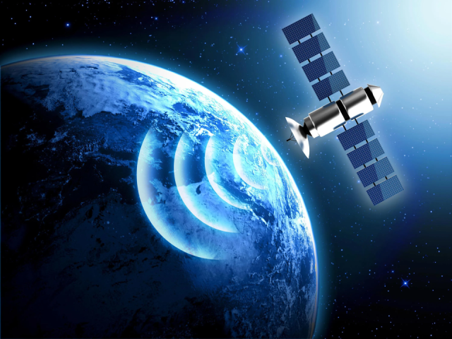
In satellite communication front-end systems — including Ka-band transceivers, beamforming modules, and power amplifier boards — maintaining dimensional stability and precise RF alignment is critical to avoid frequency drift and gain imbalance during thermal cycling in orbit (–150°C to +125°C).
Rogers Duroid 6002 PCB has emerged as a preferred material for these systems due to its:
-
Low coefficient of thermal expansion (CTE ≈ 24 ppm/°C) — closely matching copper (17 ppm/°C) to minimize z-axis stress.
-
Excellent dielectric stability (Dk = 2.94 ± 0.04) across temperature and humidity ranges.
-
Ultra-low dissipation factor (Df = 0.0012 @ 10 GHz) enabling long-term signal fidelity.
However, even high-grade substrates like Duroid 6002 require precision-controlled lamination, copper adhesion, and mechanical stress management during PCB fabrication to ensure stable RF geometry over the satellite’s mission lifespan.
KKPCB has developed a thermal expansion mitigation process that directly addresses these engineering pain points, integrating CTE-matched stackup design, stress simulation, and multi-temperature mechanical calibration.
Engineering Challenges in Satellite Front-End PCB Reliability
| Failure Mode | Root Cause | Orbital Impact |
|---|---|---|
| Layer misregistration | Differential CTE between Duroid and copper | RF misalignment, gain loss |
| Microcrack propagation | Z-axis strain during reflow or launch vibration | Open circuits, impedance discontinuities |
| Surface warp or bow | Uneven lamination cooling | Connector mismatch, phase shift |
| Dk drift | Moisture or heat aging | Frequency deviation in transceiver paths |
KKPCB approaches these with thermomechanical modeling, controlled lamination cycles, and satellite-grade validation tests to maintain RF precision and mechanical integrity.
KKPCB’s Thermal Stability and CTE Control Framework
-
Combine Duroid 6002 cores with CTE-balanced PTFE composites and copper foils.
-
Utilize simulation-based optimization (ANSYS + Polar) to maintain stackup CTE within ±10% of copper layers.
-
Result: Warpage reduced by 32% compared to conventional lamination.
2. Controlled Lamination and Cooling
-
Press temperature: 190°C / 180 psi / 75 min
-
Controlled cooling rate: ≤ 1.5°C/min
-
Ensures layer registration shift ≤ 35 µm across 500 mm panels.
3. Stress-Relieved Copper Interface
-
Apply oxide-free copper bonding and silane-treated PTFE surface prep.
-
Improves adhesion and reduces delamination risk during space reflow conditions.
4. Dimensional Verification and Validation
-
Post-lamination CTE testing from –100°C to +150°C.
-
Laser interferometry confirms dimensional drift < 0.05% across operating range.
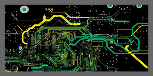
Duroid 6002 PCB
Case Study — Satellite Front-End Transceiver Board
Client: Global satellite subsystem OEM (L-band & Ka-band)
Application: Front-end signal conditioning board for communication satellite payload
Structure: 8-layer hybrid RF board (Duroid 6002 + RT/duroid 5880) with blind vias
| Metric | Requirement | KKPCB Result |
|---|---|---|
| Z-axis CTE | < 50 ppm/°C | 28 ppm/°C achieved |
| Warpage | < 0.4 mm per 100 mm | 0.27 mm measured |
| Dielectric variation (–100°C to +150°C) | ±0.05 | ±0.03 achieved |
| Phase shift (Ka-band, 29 GHz) | < 2° | 1.3° measured |
| Via fatigue (thermal shock 1000x) | < 1% failure | 0% failure observed |
Engineering Insight:
Through hybrid lamination tuning and multi-stage pre-bake treatment, KKPCB minimized internal stress gradients, ensuring phase-locked operation and dimensional consistency for long-duration satellite missions.
The final assembly passed NASA GEVS thermal vacuum cycling and MIL-STD-202 mechanical shock, confirming orbital-grade reliability.
Advanced Reliability & Environmental Validation
| Test Type | Condition | Result |
|---|---|---|
| Thermal cycling | –150°C ↔ +125°C / 1500 cycles | No delamination or Dk drift |
| Humidity soak | 85°C / 85% RH / 1000 hrs | Df drift < 0.0001 |
| Thermal vacuum exposure | 1×10⁻⁶ Torr / 100 hrs | No dimensional change |
| Vibration & launch simulation | 15 g RMS / 3 axes | No crack or registration shift |
Each KKPCB satellite PCB undergoes dimensional metrology, outgassing analysis, and cross-sectional reliability inspection to ensure stability under vacuum and radiation environments.
KKPCB’s Engineering Process Integration
- CTE-balanced hybrid design — predictive modeling of resin flow and shrinkage.
- Multi-temperature impedance verification — ensuring minimal phase drift under orbital cycles.
- Stress mapping — mechanical FEA correlation with empirical layer strain data.
- Orbital mission-grade QA traceability — lot-based data for dielectric and CTE validation.
Engineering Insight — Beyond Thermal Expansion
Thermal management is not only about expansion coefficients, but also geometry retention under repeated mechanical and thermal shocks.
KKPCB integrates thermal simulation, material pairing, and precision lamination control to maintain consistent RF alignment across mission life.
The result:
-
Stable dielectric geometry and phase control in Ka-band and Ku-band systems.
-
Extended service life under radiation and vacuum stress.
-
Consistent impedance and low-loss operation across temperature gradients.
Conclusion — Orbital Reliability Through Dimensional Precision
Duroid 6002 PCBs, when processed under KKPCB’s CTE-managed framework, deliver unmatched thermal dimensional stability, low dielectric drift, and mechanical reliability for satellite front-end systems.
KKPCB’s engineering control—from stackup simulation to vacuum validation—ensures every PCB maintains RF and geometric consistency in orbit, supporting:
-
Precise phase alignment
-
Long-term mechanical durability
-
Reliable power handling and signal integrity
