Reliability Challenges in High-Frequency Applications
In demanding industries such as automotive electronics and aerospace systems, RF PCB reliability is critical for ensuring long-term system performance under extreme operating conditions. As high-frequency PCB applications continue to expand—especially in radar systems, satellite communication, and advanced driver-assistance systems (ADAS)—materials like RO4003C PCB laminates are widely used for their stable electrical performance.
However, achieving consistent RF performance requires rigorous reliability testing and validation under harsh environmental conditions.
What is RO4003C PCB Material?
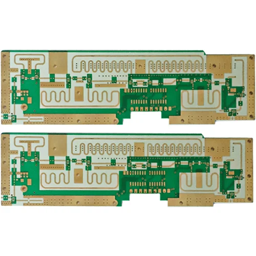
RO4003C PCB is a high-performance RF laminate designed for high-frequency PCB applications. It offers a balance between performance and manufacturability, making it suitable for both automotive and aerospace PCB systems.
Key Properties of RO4003C PCB
- Stable dielectric constant (Dk)
- Low dissipation factor (Df)
- Excellent thermal stability
- Low signal loss at high frequencies
These characteristics make RO4003C PCBs ideal for RF circuit design requiring high reliability.
Importance of RF Reliability Testing
For automotive and aerospace applications, RF reliability testing ensures that PCB performance remains stable under:
- Temperature fluctuations
- Mechanical stress
- Humidity exposure
- Long-term operation
Without proper reliability validation, even high-quality RF PCBs may fail in real-world environments.
Key Reliability Testing Methods for RO4003C PCBs
1. Thermal Cycling Testing
Thermal cycling evaluates how RO4003C PCBs perform under repeated temperature changes.
- Simulates real-world temperature variations
- Identifies material expansion and contraction issues
- Ensures stable Dk/Df performance over time
2. High-Temperature Operating Life (HTOL) Testing
This test assesses long-term reliability at elevated temperatures:
- Verifies material stability
- Evaluates long-term RF performance
- Detects early failure mechanisms
3. Humidity and Moisture Resistance Testing
Moisture can degrade RF PCB performance.
- Tests resistance to humidity absorption
- Evaluates impact on dielectric properties
- Ensures stable performance in harsh environments
4. Mechanical Stress and Vibration Testing
Critical for automotive and aerospace systems:
- Simulates vibration and shock conditions
- Ensures structural integrity of PCB assemblies
- Prevents mechanical failure
5. RF Performance Testing
Direct measurement of RF characteristics:
- Insertion loss testing
- Return loss measurement
- Signal integrity validation
Environmental Endurance in Automotive Applications
In automotive systems, RO4003C PCBs must withstand:
- Wide temperature ranges (-40°C to +125°C or higher)
- Continuous vibration
- Exposure to moisture and contaminants
Applications include:
- ADAS radar systems
- Vehicle communication modules
- Power control systems
Environmental Endurance in Aerospace Systems
In aerospace applications, requirements are even more stringent:
- Extreme temperature variations
- High altitude and pressure changes
- Radiation exposure
RO4003C PCBs are used in:
- Satellite communication systems
- Radar and navigation systems
- Avionics electronics
Design Strategies for Enhancing RF PCB Reliability
1. Material Optimization
Select high-quality RO4003C laminates with consistent properties.
2. Controlled PCB Stack-Up
Optimize multilayer PCB stack-up for:
- Stable impedance
- Reduced signal loss
- Improved thermal performance
3. Precision Manufacturing
Ensure tight control in PCB fabrication:
- Accurate lamination
- Controlled drilling and plating
- Consistent trace geometry
4. Thermal Management Design
Use effective thermal management techniques:
- Heat spreading layers
- Thermal vias
- Proper component placement
Benefits of RO4003C PCB in High-Reliability Systems
- Stable RF performance under extreme conditions
- Low signal loss and high signal integrity
- Excellent environmental endurance
- Proven reliability in automotive and aerospace applications
Conclusion: Ensuring Reliability in Harsh Environments
RO4003C PCBs provide a reliable foundation for high-frequency applications in automotive and aerospace systems. Through rigorous RF reliability testing and careful environmental validation, engineers can ensure long-term performance and system stability.
As electronic systems continue to operate in more demanding environments, advanced RF PCB materials and robust testing methodologies will be essential for success.
